48049-251-01 M-frame Circuit Breakers
02/2006
© 2003–2006 Schneider Electric All Rights Reserved
5
ENGLISH
AL1200P24K and CU1200P24K Lug Kits
RESTRAIN CABLE
For factory-installed lugs, install cable in order
listed and torque wire binding screw as
recommended on the faceplate and Table 1.
NOTE: Install bottom cables first. Bottom wire
binding screws must be fully tightened before
installing top cables. Remove foam spacer
before installing cable. If not using all lug holes,
use bottom holes first and seat screws for
unused lug holes by screwing wire binding
screws down until seated.
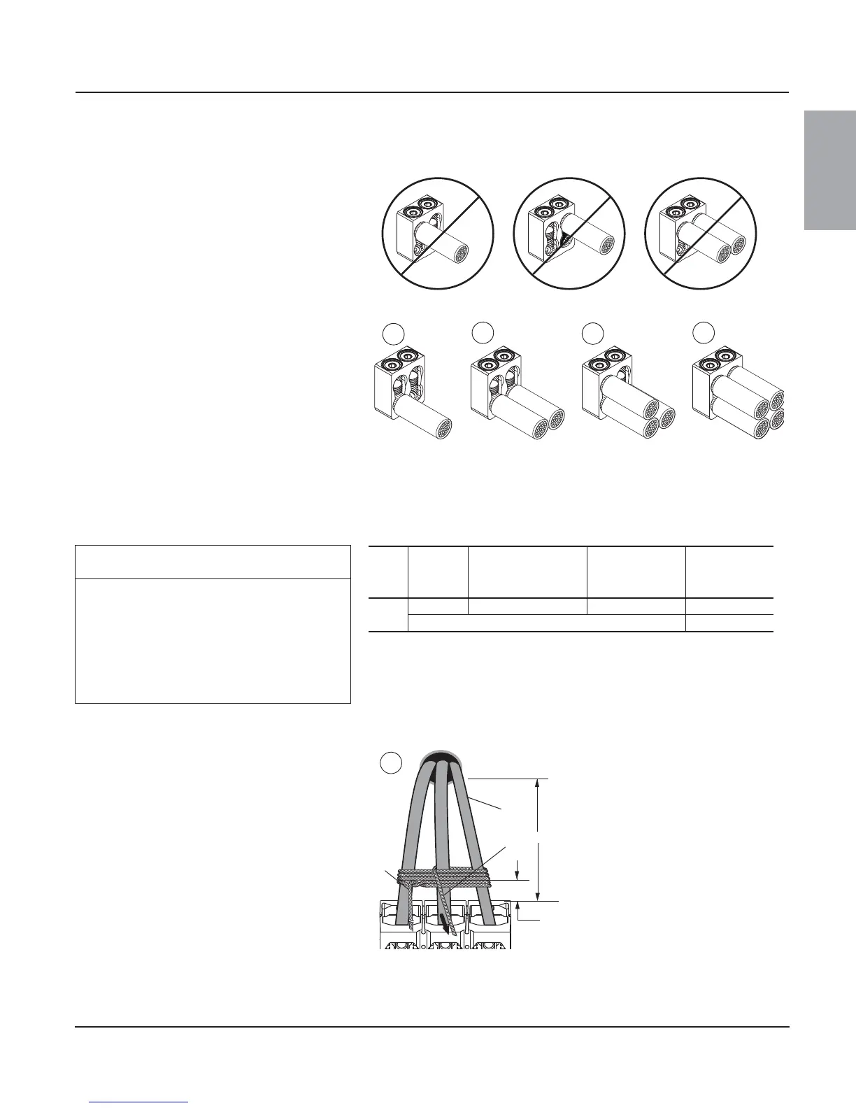
Figure 9: AL1200P24K and CU1200P24K Lug Cable Installation
1. Install left bottom cable and torque wire
binding screw.
2. Install right bottom cable and torque wire
binding screw.
3. Install left top cable and torque wire binding
screw.
4. Install right top cable and torque wire binding
screw.
For field-installable lug kits, see instruction
bulletin shipped with kit.
06123150
06123141
1
2
3
4
CAUTION
HAZARD OF CONDUCTOR MOVEMENT
UNDER SHORT-CIRCUIT CONDITIONS
Restrain circuit breaker conductors as required
in Table 2.
Failure to follow this instruction will result
in equipment damage.
Table 2: Cable Restraint Recommendations
Frame
Size
Available
Fault
Current
Conductors Used
Unsupported
Cable Length
Restraint
Recommended
800 A
≤ 65 kA Three 300 kcmil or larger ≤ 11 in. (279 mm) No*
All other cases Yes
* All requirements must be met for restraint not to be required.
Restrain circuit breaker conductors as indicated
in Table 2.
Wrap conductors using 30 ft. (9 m) of 3/8 in.
(9.5 mm) sisal rope or equivalent.
1. Begin wrapping conductors (A) 2.5 in.
(64 mm) above circuit breaker. Wrap
conductors five times, leaving 12 plus “X” ft.
(4 + “X” m) of excess rope at the first end
(B). Pull rope (C) taut.
Figure 10: Wrap Conductors
06123218
2.5 in.
[64 mm]
A
B
C
1
“X”