M-frame Circuit Breakers 48049-251-01
02/2006
© 2003–2006 Schneider Electric All Rights Reserved2
ENGLISH
I-Line
®
Circuit Breaker Installation
4. Prepare enclosure for circuit breaker (See
Figure 18 for mounting hole and cover cutout
dimensions).
— Drill mounting holes in mounting surface.
Tap holes for 10-32 threads.
— Cut opening in cover for circuit breaker
handle, handle escutcheon, accessory
cover, or accessory cover escutcheon.
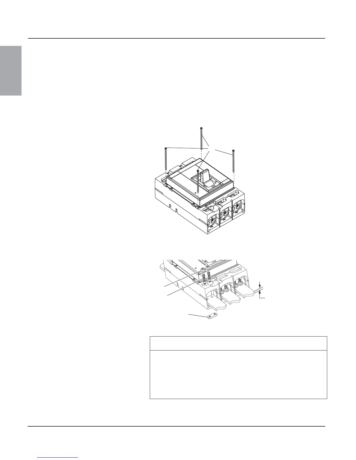
5. Mount circuit breaker using four 10-32 x
4.5 in. screws (A, provided). Torque screws
to 36 lb-in (4 N•m)
Figure 2: Mount Circuit Breaker
push
to
trip
06123086
A
6. For bus-connected circuit breakers, bolt bus
to circuit breaker by inserting bolt
(A, provided) through holes in bus into circuit
breaker nut plate (B). Secure bus with
nut (C, provided). Torque nuts to 250 in-lb
(28 N•m)
Figure 3: Install Bus
06123093
B
A
C
0.75 in.
[19 mm]
max.
1. Place circuit breaker in the tripped or off
position.
CAUTION
HAZARD OF EQUIPMENT DAMAGE
• Do not adjust jaws.
• Do not remove joint compound.
• If necessary, use Square D joint compound PJC7201.
Failure to follow this instruction can result in equipment damage.