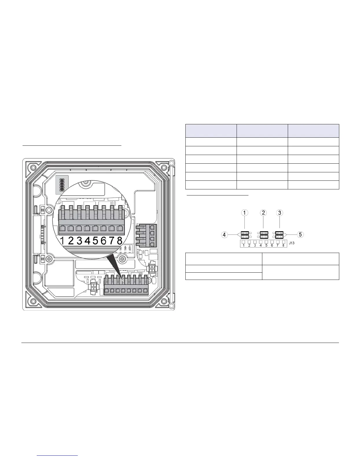
Three discrete inputs are provided for switch closure inputs or logic level
voltage inputs. Make wiring connections and configure jumper settings to
the controller as shown in Figure 9, Table 4 and Figure 10.
1ote Figure 9 sKoZs tKe EacN of tKe controller cover and not tKe inside of tKe
Pain controller coPpartPent.
Figure 9 Discrete input wiring connections
Table 4 Input connections
Discrete inputs Connector position -
Switch input
Connector position -
Voltage input
Input 1+ 3 2
Input 1- 2 3
Input 2+ 6 5
Input 2- 5 6
Input 3+ 8 7
Input 3- 7 8
Figure 10 -umper settings
1 Input 1 configuration jumpers 4 Jumpers positioned to the left for
switch inputs
2 Input 2 configuration jumpers 5 Jumpers positioned to the right for
voltage inputs
3 Input 3 configuration jumpers
1. Open the controller cover.
2. Feed the wires through the cable gland.
3. Adjust the wire as necessary and tighten the cable gland.
4. The jumpers are positioned immediately behind the connector.
Remove the connector for improved access to the jumpers and
configure the jumper settings according to the type of input as shown
in Figure 10.
5. Close the controller cover and tighten the cover screws.
6. Configure inputs in the controller.
(nglisK 19