80459-641-01E Model 6 Motor Control Centers
10/2012 Section 4—Installing the MCC
© 1999–2012 Schneider Electric All Rights Reserved
33
ENGLISH
Joining to the Right Side of an Existing
NEMA Type 3R MCC Enclosure
1. Turn off all power supplying this equipment before working on or inside
the equipment, and follow lockout/tagout procedures. Always use a
properly rated voltage sensing device to confirm the power is off.
2. Remove the end deflector (see Figure 19 on page 30) from the rightmost
section of the existing MCC and the end deflector, if supplied, from the
leftmost section of the MCC being added. Retain hardware for use in
Step 12. Discard both end deflectors.
3. Remove the back plate from the rightmost section of the existing MCC
and also from the leftmost section of the MCC being added. Retain the
back plates and mounting hardware for re-installation.
4. Remove the end plate (see Figure 19 on page 30) from the rightmost
section of the existing MCC and the end plate, if supplied, from the
leftmost section of the MCC being added. Discard both end plates.
5. Remove the insulating barrier (see Figure 20 on page 31) from the
rightmost section of the existing MCC by punching out the rivets that are
holding the barrier in place. Repeat this procedure for the barrier, if
provided, located in the leftmost section of the MCC being added.
Discard both barriers.
NOTE: Ensure that rivet parts do not fall into the MCC.
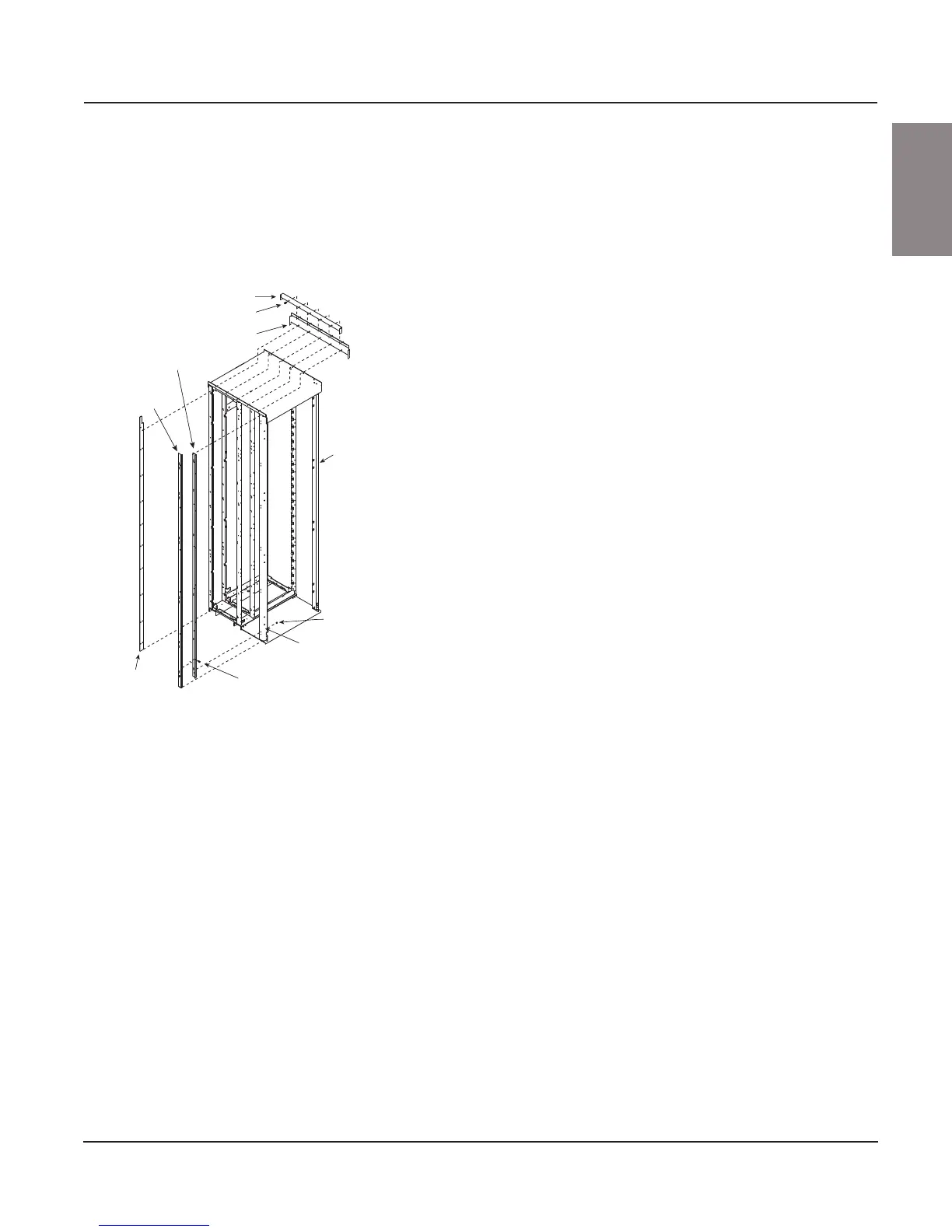
6. Install the left splice bracket (see Figure 23), 94 in. (2388 mm) long, to
the right front vertical channel of the existing MCC. Use six 10–32 hex
head screws provided in the kit. The long flange of the splice channel
will mount to the side of the vertical channel with the short flange near
the front of the vertical channel. When properly installed, the bottom of
the left splice bracket will be flush with the bottom of the vertical channel.
7. Install the right splice bracket (see Figure 23), 90 in. (2286 mm) long, to
the left splice bracket installed in Step 6 using six 10–32 flat Phillips
head screws provided in the kit. Ensure that the short flange of the right
splice bracket is in front of the flange of the left splice bracket. When
properly installed, the left splice bracket will extend approximately 1 in.
(25 mm) below the right splice bracket.
8. Position the structures that are to be spliced together. Make sure that
the fronts are flush. This ensures proper alignment of all components.
9. Splice sections using the instructions in the Model 5 Instruction Bulletin
(8998IM9101) if joining to a Model 5 MCC, or the instructions on 28 of
this instruction bulletin if joining to a Model 6 MCC. Use the 12 1/4–20
hex head screws provided in the kit to splice the corner channels of the
existing MCC to the corner channels of the new MCC.
10. Re-attach the back plate (see Figure 22 on page 32) to the leftmost
section of the MCC being added by using the 10–32 hex head screws
removed in Step 4. Install the back bracket (see Figure 23) under the back
plate using the right side holes of the back bracket. Ensure that the notch
at the top of the back bracket is installed toward the new MCC section.
11. Using the hardware removed in Step 3, re-attach the back plate (see
Figure 22 on page 32) to the rightmost section of the existing MCC.
12. Install the splice adaptor (see Figure 23) to the leftmost section of the
MCC being added by using five 1/4–20 screws provided in the kit.
13. Next, position the end deflector, provided in the kit, over the top plate
flanges of both sections (see Figure 23) and install with five 1/4–20
screws removed in Step 2.
14. Using six 10–32 hex head screws, provided in the kit, secure the right
front vertical channel of the MCC being added to the right splice bracket
installed in Step 7 (see Figure 23).
15. Before energizing the equipment, replace all covers and barriers.
Figure 23: Installing the Splice Deflector
End deflector
1/4–20 screws
Splice adaptor
Right splice bracket
(90 in. long)
Left splice bracket
(94 in. long)
Section
being
added
10-32 hex
head screw
Front
vertical
channel
10–32 flat
Phillips head screws
Back
bracket