80459-641-01E Model 6 Motor Control Centers
10/2012 Section 4—Installing the MCC
© 1999–2012 Schneider Electric All Rights Reserved
49
ENGLISH
Load and Control Wiring The top and bottom horizontal wire troughs and the vertical wire trough are
convenient areas to run incoming line, load, and control wires (see
Figure 61). Openings between sections permit wire to pass from one
section into the next for interwiring.
Control and power wires are routed to each unit via the vertical wire trough.
When supplied, grommeted wire ports must be opened to route wire to the
unit. The H-shaped cut pattern is pre-scored for easy opening. Using a
small knife, cut through the center tabs and complete the H-shaped slice
(see Figure 62). When cutting, be sure not to damage the wires located
near the grommet.
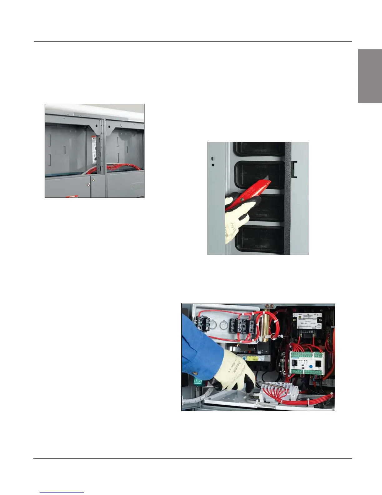
Pull-apart control terminals (see Figure 63) are mounted on a 35 mm
DIN-rail located adjacent to the wiring ports toward the front of the unit.
Terminate field control wiring on the removable portion of the block.
Figure 61: Wiring in the Top
Horizontal Wire Trough
Figure 62: Vertical Wire Trough Grommet
Figure 63: Pull-apart Type Terminal Blocks

 Loading...


