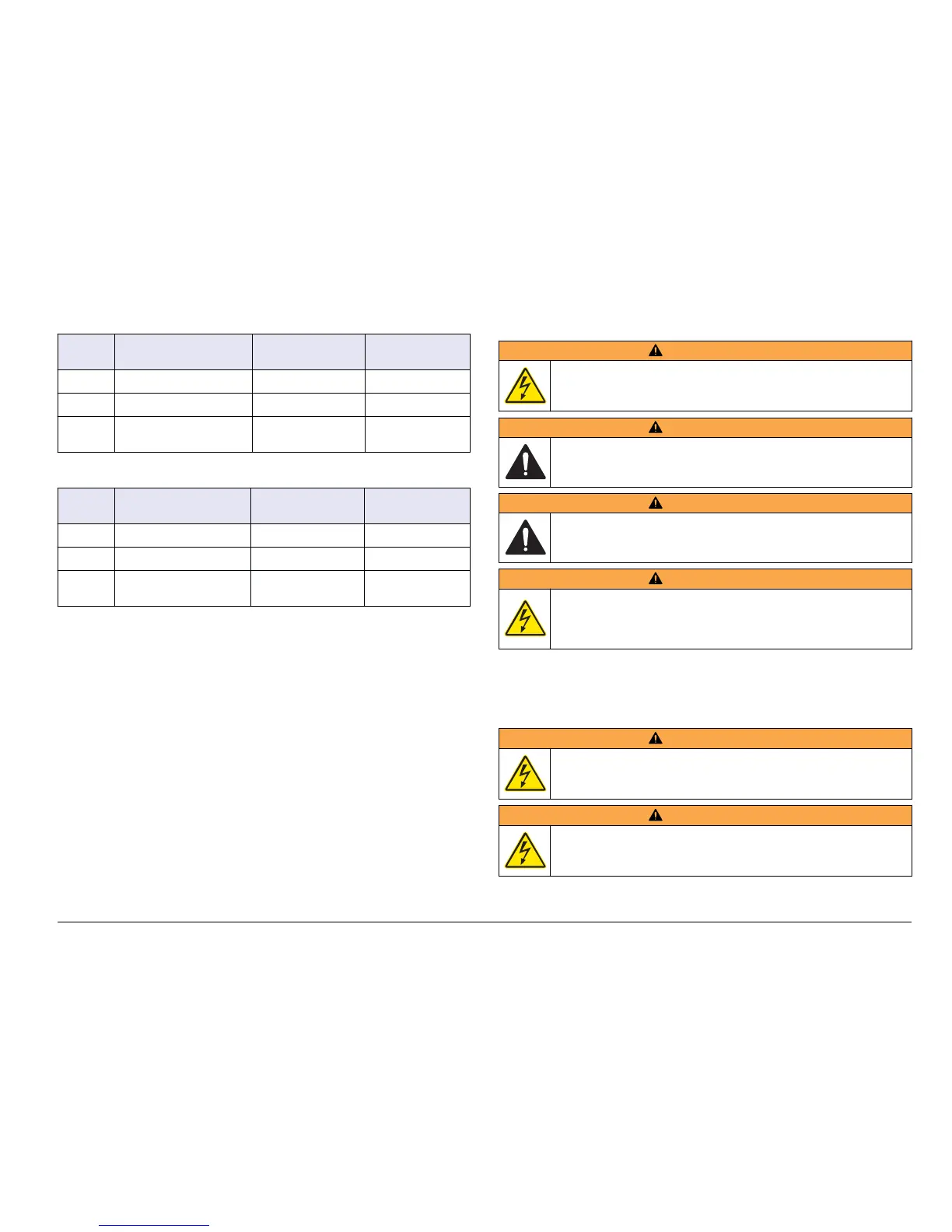
Table 1 AC power wiring information (AC powered models only)
Terminal Description
Color²North
America
Color²EU
1 Hot (L1) Black Brown
2 Neutral (N) White Blue
— Protective Earth (PE)
Ground lug
Green Green with yellow
stripe
Table 2 DC power wiring information (DC powered models only)
Terminal Description
Color²North
America
Color²EU
1 +24 VDC Red Red
2 24 VDC return Black Black
— Protective Earth (PE)
Ground lug
Green Green with yellow
stripe
Alarms and relays
The controller is equipped with four unpowered, single pole relays rated
100-250 VAC, 50/60 Hz, 5 amp resistive maximum. Contacts are rated
250 VAC, 5 amp resistive maximum for the AC powered controller and
24 VDC, 5A resistive maximum for the DC powered controller. The
relays are not rated for inductive loads.
Wiring relays
WARNING
Potential Electrocution Hazard. Always disconnect power to the
instrument when making electrical connections.
WARNING
Potential fire hazard. The relay contacts are rated 5A and are not
fused. External loads connected to the relays must have current
limiting devices provided to limit current to < 5 A.
WARNING
Potential fire hazard. Do not daisy-chain the common relay
connections or jumper wire from the mains power connection inside
the instrument.
WARNING
Potential electrocution hazard. In order to maintain the NEMA/IP
environmental ratings of the enclosure, use only conduit fittings and
cable glands rated for at least NEMA 4X/IP66 to route cables in to the
instrument.
AC line (100²250 V) powered controllers
The wiring compartment is not designed for voltage connections in
excess of 250 VAC.
24 VDC powered controllers
WARNING
Potential electrocution hazard. AC mains powered controllers
(115 V–230 V) are designed for relay connections to AC mains circuits
(i.e., voltages greater than 16 V-RMS, 22.6 V-PEAK or 35 VDC).
WARNING
Potential electrocution hazard. 24 V powered controllers are designed
for relay connections to low voltage circuits (i.e., voltages less than
16 V-RMS, 22.6 V-PEAK or 35 VDC).
(nglisK 15