M-frame Circuit Breakers 48049-251-01
02/2006
© 2003–2006 Schneider Electric All Rights Reserved8
ENGLISH
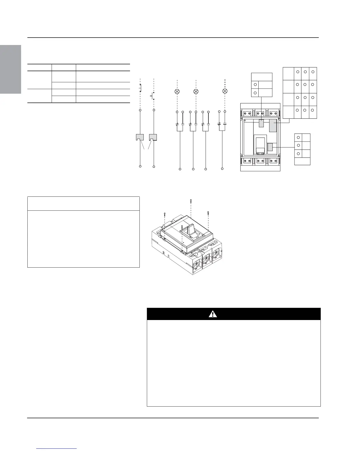
Note: All diagrams show circuit breaker in tripped position
Replace Accessory Cover
CIRCUIT BREAKER REMOVAL
Table 4: Accessory Control Wiring Diagrams
Function Connector Description
Auxiiliary
Contacts
OF
Open/Closed circuit breaker
or switch position contacts
SD Bell alarm
Remote
Operation
MN Undervoltage trip device
MX Shunt trip
or
D2
D1
MN
MX
C2
C1
06133228
22
24
21
OF2
Closed
06123229
OF3
32
34
31
Open
12
14
OF1
11
92
94
91
SD
Tripped
Remote Operation
Alarm Contacts
D1/C1
D2/C2
MN/MX
OF1
OF2
OF3
SD
11
21
31
91
12
22
32
92
14
24
34
94
06123230
82
81
SDE
84
CAUTION
HAZARD OF EQUIPMENT DAMAGE
Accessory cover must be secured with all four
screws tightened to stated torque. Do not
overtorque screws. Do not use power
equipment to torque screws.
Failure to follow this instruction can result
in equipment damage.
Replace accessory cover. Replace all four
accessory cover screws. Hand tighten screws to
11–13 lb-in (1.2–1.5 N•m). Do not exceed torque
specification of screws.
Figure 15: Replace Accessory Cover
06123225
Turn off all power supplying this equipment
before working on or inside equipment.
Remove circuit breaker in reverse order of
installation.
DANGER
HAZARD OF ELECTRIC SHOCK, EXPLOSION OR ARC FLASH
• Apply appropriate personal protective equipment (PPE) and follow safe
electrical work practices. See NFPA 70E.
• This equipment must be installed and serviced only by qualified electrical
personnel.
• Turn off all power supplying this equipment before working on or inside
equipment.
• Always use a properly rated voltage sensing device to confirm power is off.
• Replace all devices, doors and covers before turning on power to this
equipment.
Failure to follow this instruction will result in death or serious injury.