Intel
®
EP80579 Integrated Processor Product Line—Sideband Signals
Intel
®
EP80579 Integrated Processor Product Line
Platform Design Guide May 2010
256 Order Number: 320068-005US
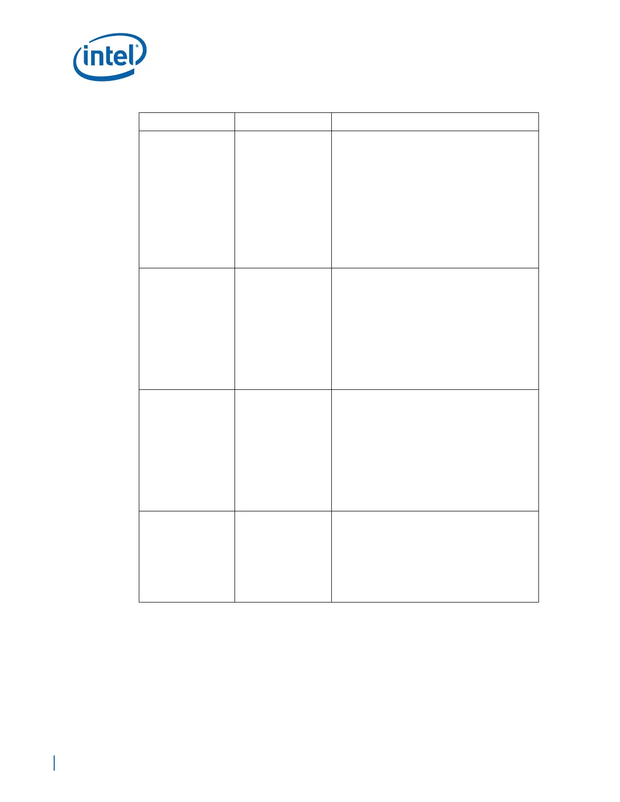
RCIN# CPU Sideband Input
Keyboard Controller Reset Processor:
• The keyboard controller can generate INIT# to the
CPU. This saves the external OR gate of other
sources of INIT#. When EP80579 detects the
assertion of this signal, INIT# is generated for 16
PCICLK clocks.
• EP80579 ignores RCIN# assertion during
transitions to the S3, S4 and S5 states.
• Connect to Keyboard Reset (KBDRST#) pin of the
Keyboard Controller provided by the Super I/O
device.
Note:
• This signal should be pulled-up to VCC3 (3.3V)
using a 10KΩ ± 5% resistor.
A20GATE CPU Sideband Input
A20 Gate:
• A signal from the keyboard controller. Acts as an
alternative method to force the A20M# signal
active. Saves the external OR gate needed with
various other chipsets.
• Connect to A20M pin of the Keyboard Controller
provided by the Super I/O device.
• Pull up signal to Platform 3.3V (VCC3) power supply
using
10KΩ ± 5% resistor
Note:
• This signal should be pulled-up to VCC3 (3.3V)
using a 10KΩ ± 5% resistor if not used
CPURST# CPU Sideband Output
Processor Bus Reset:
• The IMCH assets CPURST# while RSTIN# is
asserted and for approximately 1 ms after RSTIN#
is deasserted. The CPURST# allows the processor
to begin execution in a known state.
• Processor reset output signal that can be used by a
debug tool.
• Pull up signal to Platform 3.3V (VCC3) power supply
using 10KΩ ± 5% resistor if used.
Note:
• This signal can be left as a no connect (NC) if not
used
CPUPWRGD_OUT CPU Sideband Output
CPU Power Good:
• This EP80579 output signal is made visible to the
platform for debug purposes only. This signal is an
open drain signal, and requires an external pull-up
resistor. CPUPWRGD monitors an internal signal
connected directly form the IICH to the processor
and represents a logical AND of PWROK and
VRMPWRGD signals
• Pull up signal to Platform 3.3V (VCC3) power supply
using
10KΩ ± 5% resistor
Table 92. Sideband Signals (Sheet 3 of 4)
Signal Name Group Description

 Loading...


