Organization/Visualization point clouds
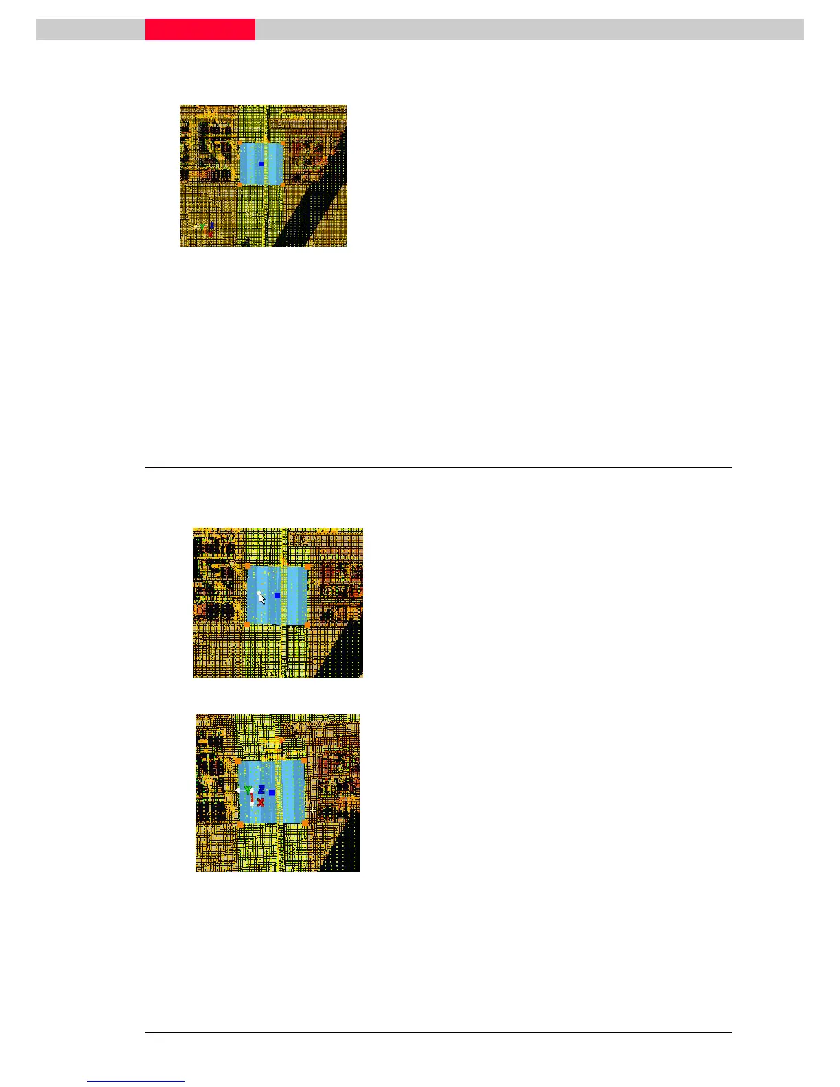
Figure 38
•
Make sure the patch is selected, look up the status bar
View | Coordinate System | Set to Object
View | Coordinate System | Set to ObjectView | Coordinate System | Set to Object
View | Coordinate System | Set to Object
The User Coordinate System is aligned to the
selected patch, which means z is aligned to
the patch normal, i.e. perpendicular to its
surface.
Since the UCS was re-aligned, but not moved it is still at its original origin. Zoom
out to see the rotation of the z-axis.
Each object defines an axis in a different way. Selecting e.g. a cylinder defines z
along its centerline.
An alternative way is using the command View | Coordinate System | Set
View | Coordinate System | Set View | Coordinate System | Set
View | Coordinate System | Set Using
Using Using
Using
One Axis
One AxisOne Axis
One Axis
or View | Coordinate System | Set
iew | Coordinate System | Set iew | Coordinate System | Set
iew | Coordinate System | Set Using Two Axes.
Using Two Axes.Using Two Axes.
Using Two Axes.
5.5 Set the Coordinate System's Origin at a Picked Point
Next move the origin to a selected point. This command is practically the same as 5.2 with just
one pick-point selected, but without the option to set an offset.
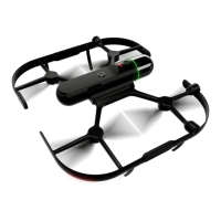
Figure 39
•
Pick
PickPick
Pick a point on the patch
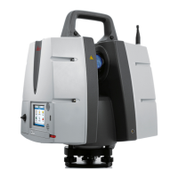
Figure 40
•
View | Coordinate System | Set Origin
View | Coordinate System | Set OriginView | Coordinate System | Set Origin
View | Coordinate System | Set Origin
This command sets the coordinate system's
origin at the picked point whilst keeping its
current orientation.