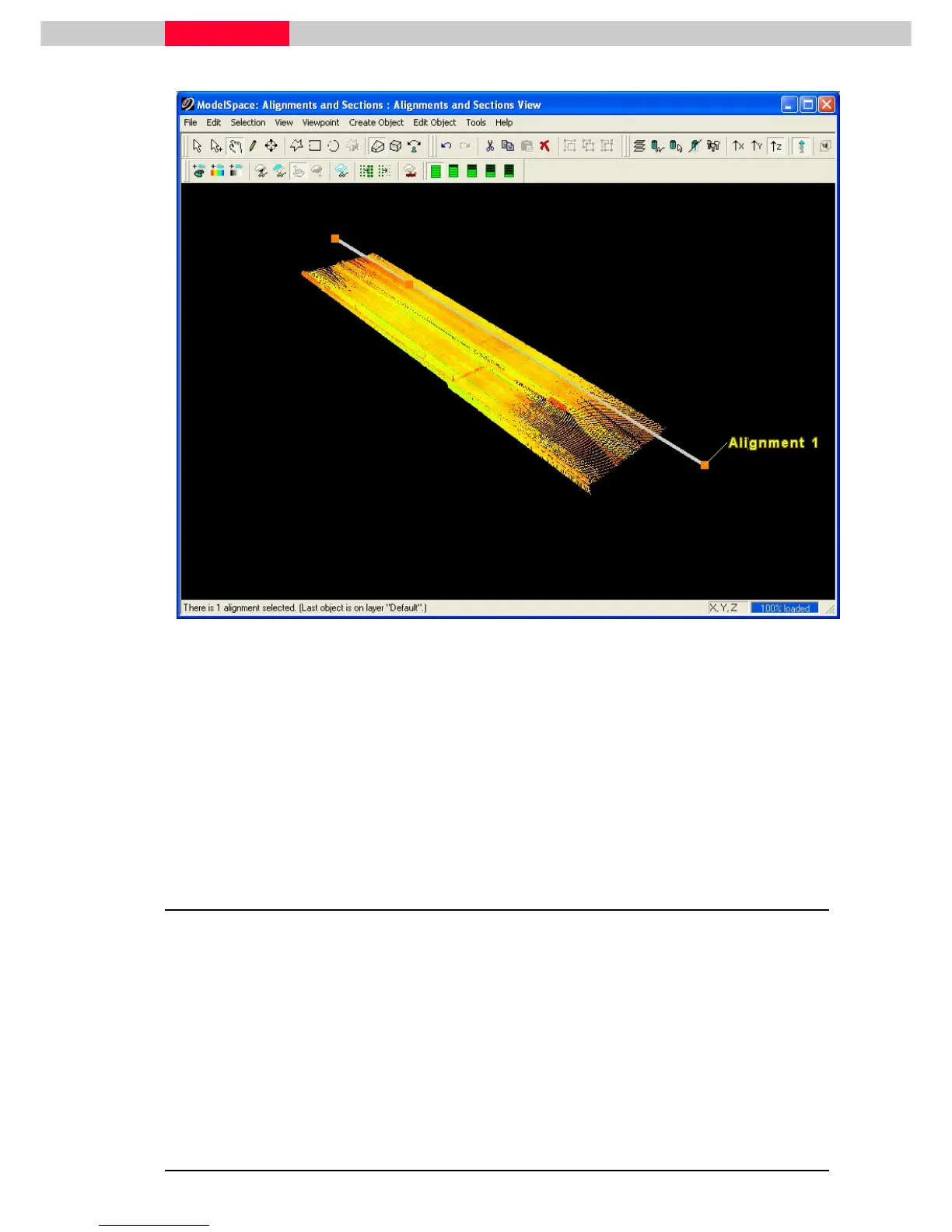
Figure 21
•
If the start station is assigned to the wrong end, click
Tools |Alignment and Section | Switch Alignment Start/End.
•
When multiple objects are selected, such as this case, the objects must be geometrically
connected in a single unbroken sequence. The object picked last provides the end-point at
which the starting station is assigned.
•
Alignments may be horizontal, skewed, or a mixture of both, but may not be vertical.
4 Create Sections
As you progress along an alignment, the station numbers increase. A station is a point along the
alignment at which a section is created.
•
All features to the right of the alignment have a positive “offset”, and all the features to the
left have a negative “offset”, relative to the 2d coordinate system.
•
For each
Cross Section
created the local coordinate system is oriented with Y=up, +X to the
right, -Z tangent (in line and away from the alignment).
•
The offsets are represented as absolute values, appended by “L” for left, or “R” for right).
Each feature also has a vertical “elevation” in the local coordinate system.