18 - 28 Module 5.2 - Mesh Data Extraction
Figure 21
•
Select all contour lines to be reduced.
(Selection | Set Selectable
Selection | Set SelectableSelection | Set Selectable
Selection | Set Selectable select Contours
ContoursContours
Contours)
•
Go to Tools
Tools Tools
Tools |
||
| Contours
Contours Contours
Contours |
||
| Decimate
Decimate Decimate
Decimate and the
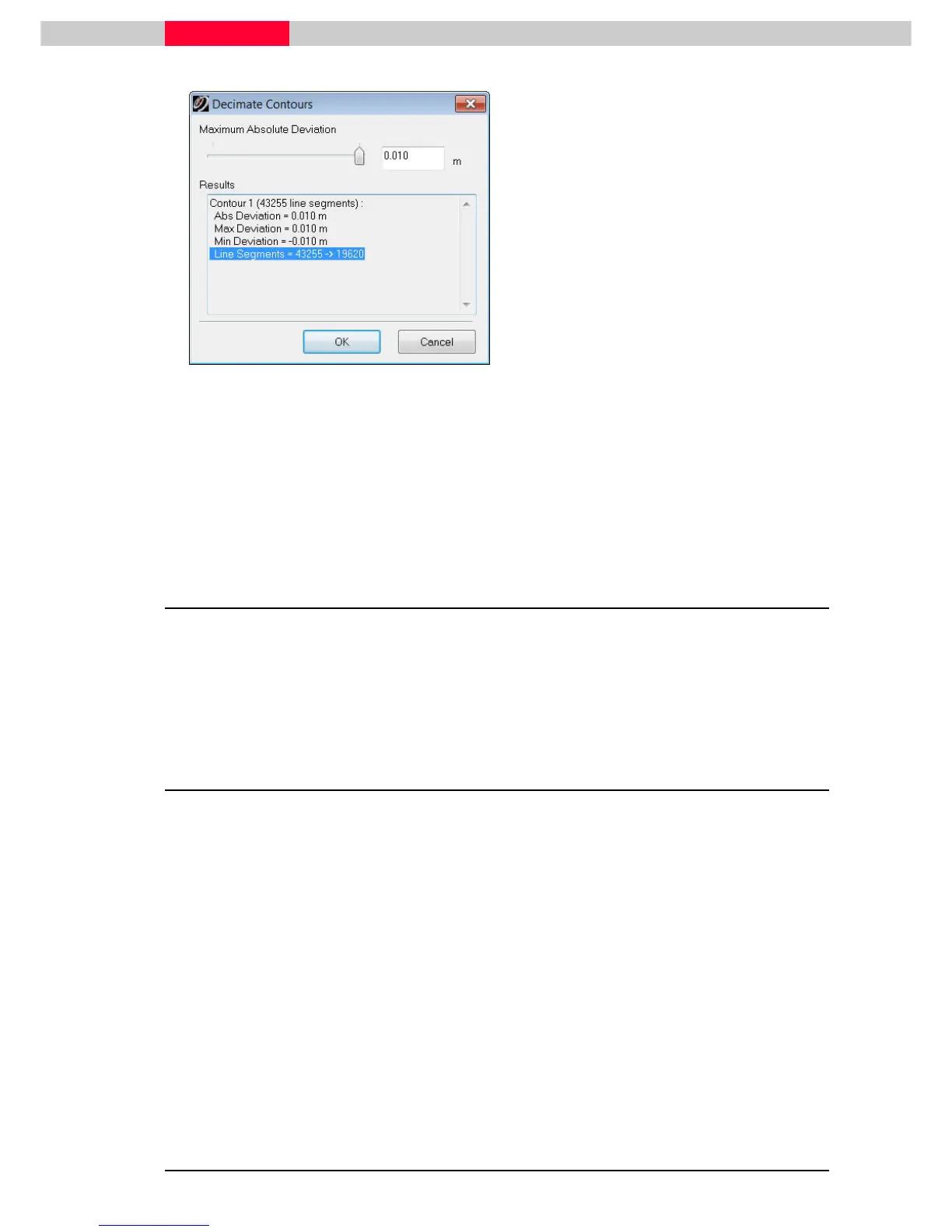
Decimate Contours dialog appears.
•
The maximum absolute deviation can be set
by either entering a value (press TAB to
update) or by moving the slider.
•
View the number of line segments changing
in the lower half of the window.
•
Set this value to 10mm and press OK.
The contours are now redrawn.
A good workflow is to first decimate the actual mesh prior to creating the
contours.
Contours can now be exported via coe or dxf.
3 Enhanced TIN Mesh Creation and Editing
Using a new dataset “ImolaBridge.imp”, the following will look at using the actual mesh as a
deliverable and how to enhance this by integrating breaklines into. Afterwards the mesh will be
reduced maintaining those breaklines and the actual surface quality. This can be useful when an
export of the created triangulation to another CAD package is required.
3.1 Defining Breaklines
A breakline is a feature line or polyline representing a ridge or some other feature that the user
wishes to preserve in a mesh made up of triangular elements. A breakline can be considered a
series of edges to which the triangles should conform to i.e. not intersect.
Breaklines usually represent a change in geographic shape or configuration such as a curb, a
trough, or some geometric feature that has a distinct characteristic setting it apart from
adjacent topography or features.
We are going to create a break line along the south curb of the road. Creating a break line is a
useful way to keep the integrity of a surface characteristic intact during decimation, i.e. a curb
top or gutter.
•
Using the database ImolaBridge.imp, open the ModelSpace View called
Cleaned Unified
ModelSpace For Mesh Creation.