4 Special Functions
3-66 SmartAXIS Touch User's Manual
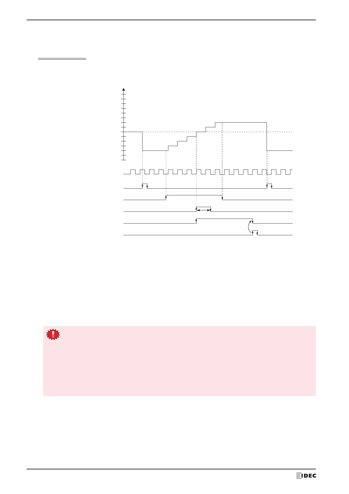
● Timing chart 1
Single-phase high-speed counter (group 5) timing chart
Operating conditions
One preset value is used, and when the values match, output Q1 turns on and the current value is kept.
Overflow and underflow are not used.
1 When reset input (M8175) turns on, the reset value (D8144, D8155) is stored in the current value (D8140, D8141).
2 When gate input (M8174) turns on, the counting begins.
3 When the current value (D8140, D8141) and preset value 1 (D8142, D8143) match, the preset value 1 comparison
output (Q1) and Comparison ON status (M8176) turn on. When the Keep check box is selected in the settings in the
WindLDR High-speed Counter Settings, the current value is kept.
4 Q1 maintains the on state until comparison output reset (M8173) turns on. Preset value Comparison ON status
(M8176) turns on for only one scan.
5 When the gate output turns off, counting stops.
Current value (D8140, D8141)
Preset value 1=6
(D8142, D8143)
Pulse input I5
Q1
M8175
M8174
M8173
M8176
(D8144, D8145)
Gate input
Preset value
Comparison ON status
Reset input
One scan
Comparison output
reset
Preset value 1
Comparison output
14
13
12
11
10
9
8
7
6
5
4
3
2
1
0
Reset value=2
Reset
High-speed counter usage precautions
The high-speed counter starts the count operation with the following two conditions.
• The Touch starts operation.
• The gate input is turned on.
To start the count operation, turn the gate input on from off when the Touch is running. When the gate
input is already on when the Touch is stopped, the count operation starts when the Touch is switched from
stop to run.
When a ladder program or FBD program is downloaded during the count operation, the count operation
stops. The count operation will restart by setting the Touch to run.