SmartAXIS Touch User's Manual 27-1
27
Internal Devices
This chapter describes internal devices available for the SmartAXIS.
The Touch includes an internal HMI device to control HMI functions, and control device for control functions.
1.1 HMI Device Addresses
■ HMI Internal Relay (LM)
This is a bit-unit device used for the HMI function. It can store 2,048 addresses.
■ HMI Keep Relay (LK)
This is a bit-unit device that holds the values of device used for the HMI function. The value of this device can be set
to 0 by clearing the project data download option or online function, or it becomes zero if the backup battery is
drained. The address range can be varied between 1,024 and 8,192. For details, refer to Chapter 16 “Minimum and
Maximum Amount of Data Storage and Number of Addresses” on page 16-2.
■ HMI Temporary Relay (LBM)
This is a bit-unit device for temporarily storing values for the HMI function. The value of this device switches between
screens and text groups and user accounts, and it becomes 0 if the screen is reset. It can store 128 addresses.
■ HMI Special Internal Relay (LSM)
Special functions are assigned to each bit by the bit-unit device. It can store 64 addresses.
Chapter 27 Internal Devices
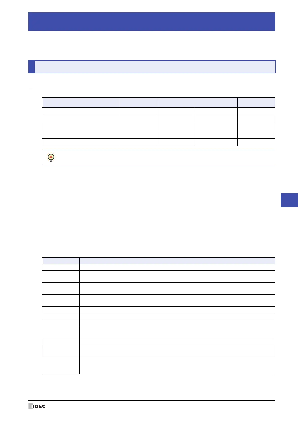
1Bit Devices
Internal Device Name Symbol R/W Address Range Base
HMI Internal Relay LM R/W 0 to 2,047 10
HMI Keep Relay LK R/W Variable 10
HMI Temporary Relay LBM R/W 0 to 127 10
HMI Special Internal Relay LSM R/W 0 to 63 10
HMI Timer Relay LTC R 0 to 31 10
R/W stands for Read/Write. R/W enables reading and writing of values, whereas R enables reading only.
Address Function/Part
LSM0 Normally set to 1.
LSM1
1 only on the second scan when Base Screen is switched.
It also operates when switching text group or user account, or resetting the display screen.
LSM2
1 only on the first scan when Base Screen is switched.
It also operates when switching text group or user account, or resetting the display screen.
LSM3
0 only on the first scan when Base Screen is switched.
It also operates when switching text group or user account, or resetting the display screen.
LSM4 Alternates between 0 and 1 on each scan of the Touch.
LSM5 1 only on the first scan when Popup Screen is opened.
LSM6 1 while touch panel is pressed.
LSM7
Alternates between 0 and 1 each time data is read (read scan) from all the external devices being
used.
LSM8 After powering ON value is 1 until the initially displayed screen switches to another screen.
LSM9
When value changes from 0 to 1, the backup data stored in flash memory is restored.
When it becomes 1 value does not become 0 until the Touch is reset or 0 is written.
LSM10
When value changes from 0 to 1, the data of Keep Relay and Keep Register configured in the Data
Storage Area, and the current backlight settings are transferred to flash memory.
When it becomes 1 value does not become 0 until the Touch is reset or 0 is written.