SmartAXIS Touch User's Manual 3-73
4 Special Functions
3
Project
● Procedure
1
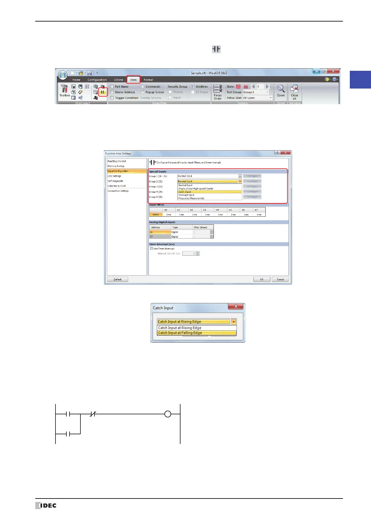
On the WindO/I-NV3 View tab, in the Workspace group, click (Control Function).
WindLDR starts.
2 On the WindLDR Configuration tab, in the Function Area Settings group, click Input & Output Configuration.
The Function Area Settings dialog box is displayed.
3 Select Catch Input in the Groups 1 through 6 pull-down list boxes.
The Catch Input dialog box is displayed.
4 Select Catch Input Rising Edge or Catch Input Falling Edge in the pull-down list, and then click OK.
5 Click OK.
This concludes configuring the settings.
●
Example: Maintaining Catch Input
When a catch input is received, the catch input relay assigned to a catch input is turned on for only one scan.
This example demonstrates a program to maintain a catch input status for more than one scan.
Input I2 is designated as a catch input using the
Function Area Settings.
When input I2 is turned on, special internal relay
M8091 is turned on, and M0000 is maintained in
the self-holding circuit.
When NC input M1 is turned off, the self-holding
circuit is unlatched, and M0 is turned off.
M0 is used as an input condition for the
subsequent program instructions.