2 Ladder Program
12-12 SmartAXIS Touch User's Manual
Monitor Operation
Another powerful function of WindLDR is to monitor the PLC operation on the computer. The input and output status
of the sample program can be monitored in the ladder diagram.
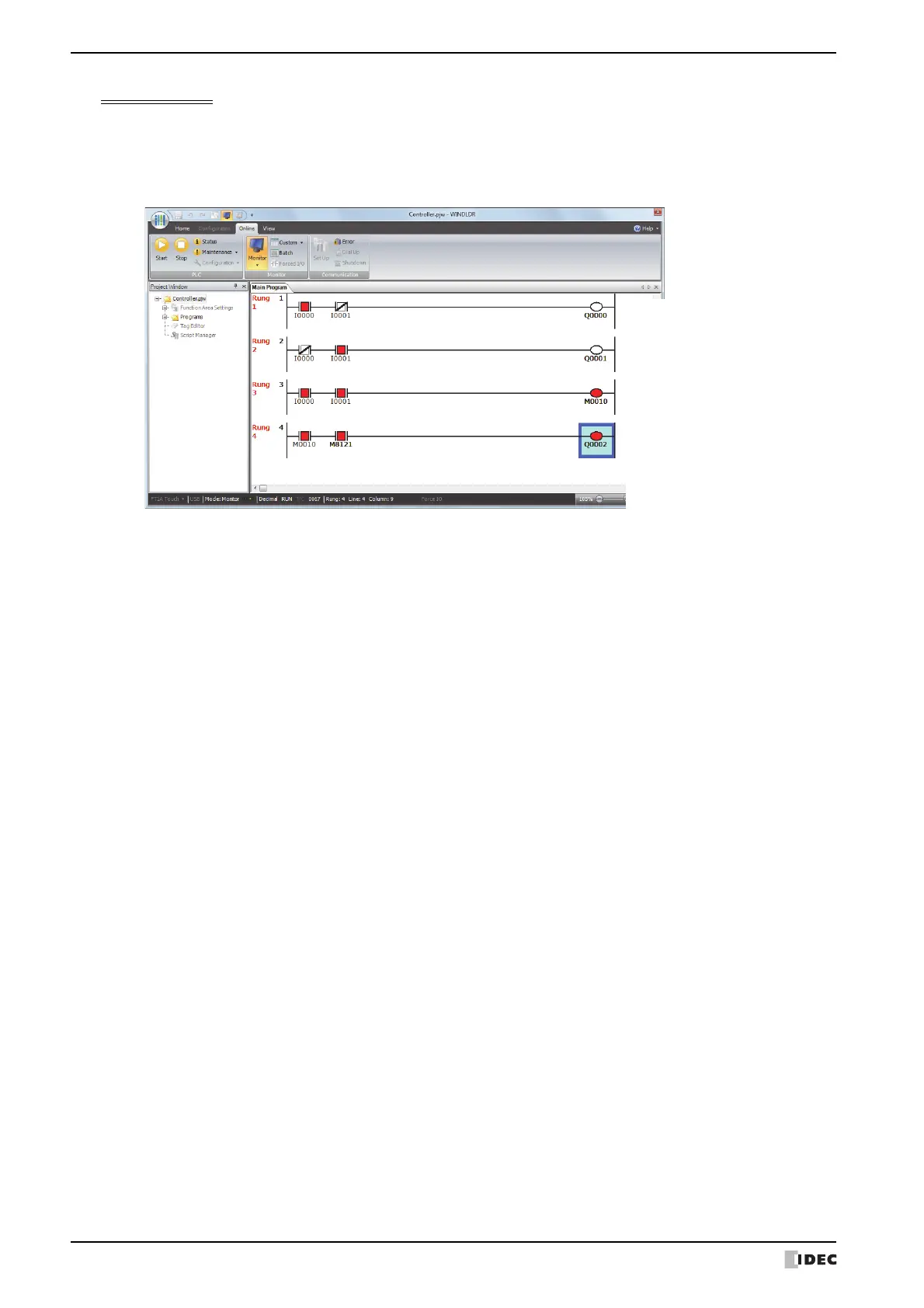
On the WindLDR Online tab, in the Monitor group, click Monitor.
When both inputs I0 and I1 are on, the ladder diagram on the monitor screen looks as follows:
Rung 1:
When both inputs I0 and I1 are on,
output Q0 is turned off.
Rung 2:
When both inputs I0 and I1 are on,
output Q1 is turned off.
Rung 3:
When both inputs I0 and I1 are on,
internal relay M10 is turned on.
M8121 is the 1-sec clock special
internal relay.
While M10 is on, output Q2 flashes in
1-sec increments.