2 Ladder Program
12-22 SmartAXIS Touch User's Manual
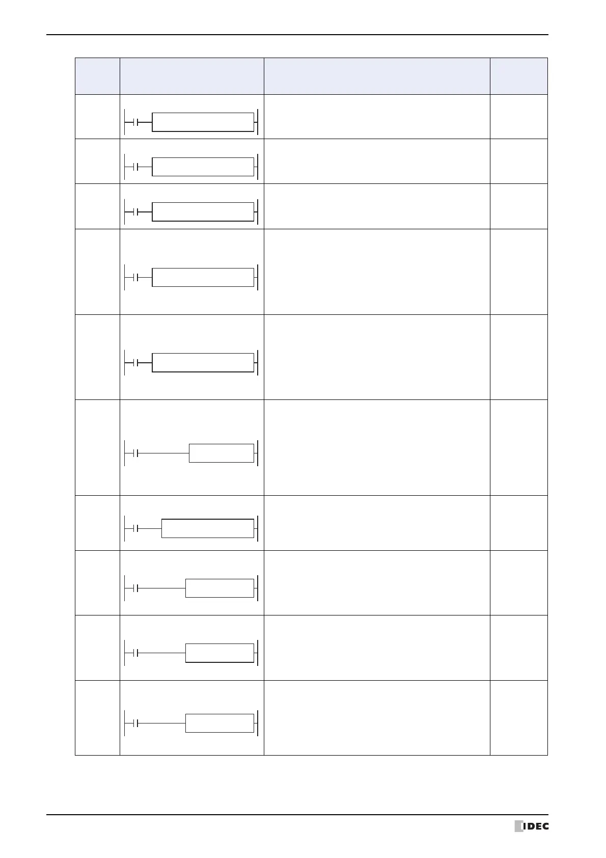
ANDW
AND Word
When input is on, 16- or 32-bit data designated by
source devices S1 and S2 are ANDed, bit by bit. The
result is set to destination device D1.
S1 · S2 → D1
YES
ORW
OR Word
When input is on, 16- or 32-bit data designated by
source devices S1 and S2 are ORed, bit by bit. The result
is set to destination device D1.
S1 + S2 → D1
YES
XORW
Exclusive OR Word
When input is on, 16- or 32-bit data designated by
source devices S1 and S2 are exclusive ORed, bit by bit.
The result is set to destination device D1.
→ D1
YES
SFTL
Shift Left
When input is on, N_B-bit data string starting with
source device S1 is shifted to the left by the quantity of
bits designated by device Bits.
The result is set to source device S1, and the last bit
status shifted out is set to a carry (special internal relay
M8003). Zero or 1 designated by source device S2 is set
to the LSB.
CY ← S1
YES
SFTR
Shift Right
When input is on, N_B-bit data string starting with
source device S1 is shifted to the right by the quantity of
bits designated by device Bits.
The result is set to source device S1, and the last bit
status shifted out is set to a carry (special internal relay
M8003). Zero or 1 designated by source device S2 is set
to the MSB.
S1 → CY
YES
BCDLS
BCD Left Shift
When input is on, the 32-bit binary data designated by
S1 is converted into 8 BCD digits, shifted to the left by
the quantity of digits designated by S2, and converted
back to 32-bit binary data.
Valid values for each of S1 and S1+1 are 0 through
9999.
The quantity of digits to shift can be 1 through 7.
Zeros are set to the lowest digits as many as the digits
shifted.
YES
WSFT
Word Shift
When input is on, N blocks of 16-bit word data starting
with device designated by D1 are shifted up to the next
16-bit positions. At the same time, the data designated
by device S1 is moved to device designated by D1. S2
specifies the quantity of blocks to move.
YES
ROTL
Rotate Left
When input is on, 16- or 32-bit data of the designated
source device S1 is rotated to the left by the quantity of
bits designated by device bits.
The result is set to the source device S1, and the last bit
status rotated out is set to a carry (special internal relay
M8003).
YES
ROTR
Rotate Right
When input is on, 16- or 32-bit data of the designated
source device S1 is rotated to the right by the quantity of
bits designated by device
bits.
The result is set to the source device S1, and the last bit
status rotated out is set to a carry (special internal relay
M8003).
YES
HTOB
Hex to BCD
When input is on, the 16- or 32-bit data designated by
S1 is converted into BCD and stored to the destination
designated by device D1.
Valid values for the source device are 0 through 9999 for
the word data type, and 0 through 9999 9999 for the
double-word data type.
S1 → D1
YES
Symbol Name and Diagram Function
Interrupt
Program
Execution
S2(R)
*****
S1(R)
*****
ANDW(*) S3(R)
*****
REP
**
S2(R)
*****
S1(R)
*****
ORW(*) S3(R)
*****
REP
**
S2(R)
*****
S1(R)
*****
XORW(*) S3(R)
*****
REP
**
S2
*****
S1
*****
SFTL N_B
*****
bits
**
S2
*****
S1
*****
SFTR N_B
*****
bits
**
S2
*****
S1
*****
WSFT D1
*****