2 Ladder Program
12-24 SmartAXIS Touch User's Manual
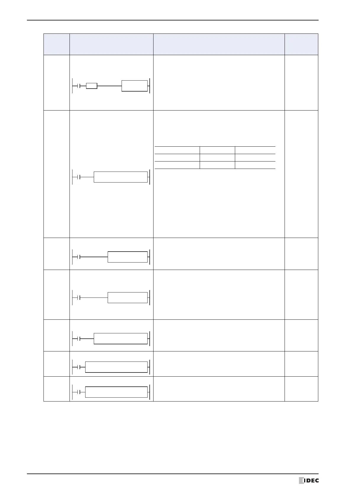
ALT
Alternate Output
When input is turned on, output, internal relay, or shift
register bit designated by D1 is turned on and remains
on after the input is turned off.
When input is turned on again, the designated output,
internal relay, or shift register bit is turned off.
The ALT instruction must be used with a SOTU or SOTD
instruction, otherwise the designated output, internal
relay, or shift register bit repeats to turn on and off in
each scan.
YES
CVDT
Convert Data Type
When input is on, the data type of the 16- or 32-bit data
designated by S1 is converted and stored to the
destination designated by device D1.
Data types can be designated for the source and
destination, separately.
When the same data type is designated for both source
and destination, the CVDT instruction has the same
function as the MOV instruction.
Unless F (float) data type is selected for both source and
destination, only the integral number is moved, omitting
the fraction.
When the source data exceeds the range of destination
data type, the destination stores a value closest to the
source data within the destination data type.
S1 → D1
YES
DTDV
Data Divide
When input is on, the 16-bit binary data designated by S1
is divided into upper and lower bytes. The upper byte
data is stored to the destination designated by device D1.
The lower byte data is stored to the device next to D1.
S1 → D1, D1+1
YES
DTCB
Data Combine
When input is on, the lower-byte data is read out from 2
consecutive sources starting with device designated by
S1 and combined to make 16-bit data. The lower byte
data from the first source device is moved to the upper
byte of the destination designated by device D1, and the
lower byte data from the next source device is moved to
the lower byte of the destination.
S1, S1+1 → D1
YES
SWAP
Data Swap
When input is on, upper and lower byte- or word-data of
a word- or double-word-data designated by S1 are
exchanged, and the result is stored to destination
designated by D1.
S1 → D1
YES
WEEK
Weekly Timer
Specified day of the week and ON time and OFF time are
compared with the current day/time, and the result is
output
NO
YEAR
Yearly Timer
Specified date and current date are compared and result
is output
NO
Symbol Name and Diagram Function
Interrupt
Program
Execution
D1 (R)
*****
S1 (R)
*****
CVDT
*TO*
REP
**
Data Type W, I D, L, F
Source S1 S1·S1+1
Destination D1 D1·D1+1
D1 (R)
*****
S1 (R)
*****
SWAP(*) REP
**
D1
*****
S2
*****
WEEK S1
*****
S3
*****
D1
*****
S2
*****
YEAR S1
*****
S3
*****