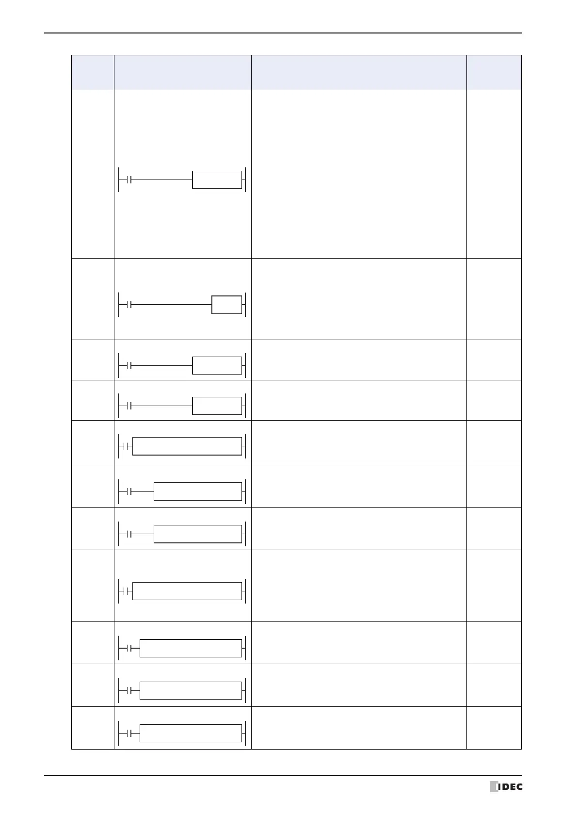
2 Ladder Program
12-26 SmartAXIS Touch User's Manual
IOREF
I/O Refresh
When input is on, 1-bit I/O data designated by source
device S1 is refreshed immediately regardless of the scan
time.
When I (input) is used as S1, the actual input status is
immediately read into an internal relay starting with
M300 allocated to each input available on the CPU
module.
When Q (output) is used as S1, the output data in the
RAM is immediately written to the actual output available
on the CPU module.
Refresh instructions are useful when a real-time
response is required in a user program which has a long
scan time. The refresh instruction is most effective when
using the refresh instruction at a ladder step immediately
before using the data.
The IOREF instruction can be used with an interrupt
input or timer interrupt to refresh data.
YES
HSCRF
High-speed Counter Refresh
When input is on, the HSCRF instruction refreshes the
high-speed counter current values in special data
registers in real time.
The current values of four high-speed counters HSC1
through HSC4 are usually updated in every scan. The
HSCRF can be used in any place in the ladder diagram
where you want to read the updated high-speed counter
current value.
YES
DI
Disable Interrupt
When input is on, interrupt inputs and timer interrupt
designated by source device S1 are disabled.
NO
EI
Enable Interrupt
When input is on, interrupt inputs and timer interrupt
designated by source device S1 are enabled.
NO
XYFS
XY Format Set
When input is on, the format for XY conversion is set.
The XY coordinates define the linear relationship
between X and Y.
NO
CVXTY
Convert X to Y
When input is on, the X value designated by device S2 is
converted into corresponding Y value according to the
linear relationship defined in the XYFS instruction. The
conversion result is set to the device designated by D1.
NO
CVYTX
Convert Y to X
When input is on, the Y value designated by device S2 is
converted into corresponding X value according to the
linear relationship defined in the XYFS instruction. The
conversion result is set to the device designated by D1.
NO
AVRG
Average
When input is on, sampling data designated by device S1
is processed according to sampling conditions designated
by devices S2 and S3.
When sampling is complete, average, maximum, and
minimum values are stored to 3 consecutive devices
starting with device designated by D1, then sampling
completion output designated by device D2 is turned on.
NO
DTML
1-sec Dual Timer
While input is on, destination device D1 repeats to turn
on and off for a duration designated by devices S1 and
S2, respectively.
The time range is 0 through 65535 sec.
NO
DTIM
100-msec Dual Timer
While input is on, destination device D1 repeats to turn
on and off for a duration designated by devices S1 and
S2, respectively.
The time range is 0 through 6553.5 sec.
NO
DTMH
10-msec Dual Timer
While input is on, destination device D1 repeats to turn
on and off for a duration designated by devices S1 and
S2, respectively.
The time range is 0 through 655.35 sec.
NO
Symbol Name and Diagram Function
Interrupt
Program
Execution
Yn
*****
Xn
*****
S1
*
XYFS(*) Y0
*****
X0
*****
.....
S2
*****
S1
*****
CVXTY(*) D1
****
S2
*****
S1
*****
CVYTX(*) D1
****
D2
*****
D1
*****
AVRG(*) S3
*****
S2
*****
S1
*****
D2
*****
S2
*****
DTML S1
*****
D1
*****
D2
*****
S2
*****
DTIM S1
*****
D1
*****
D2
*****
S2
*****
DTMH S1
*****
D1
*****