Intel
®
EP80579 Integrated Processor Product Line May 2010
Order Number: 320068-005US 212
Gigabit Ethernet (GbE) Interface—Intel
®
EP80579 Integrated Processor Product Line
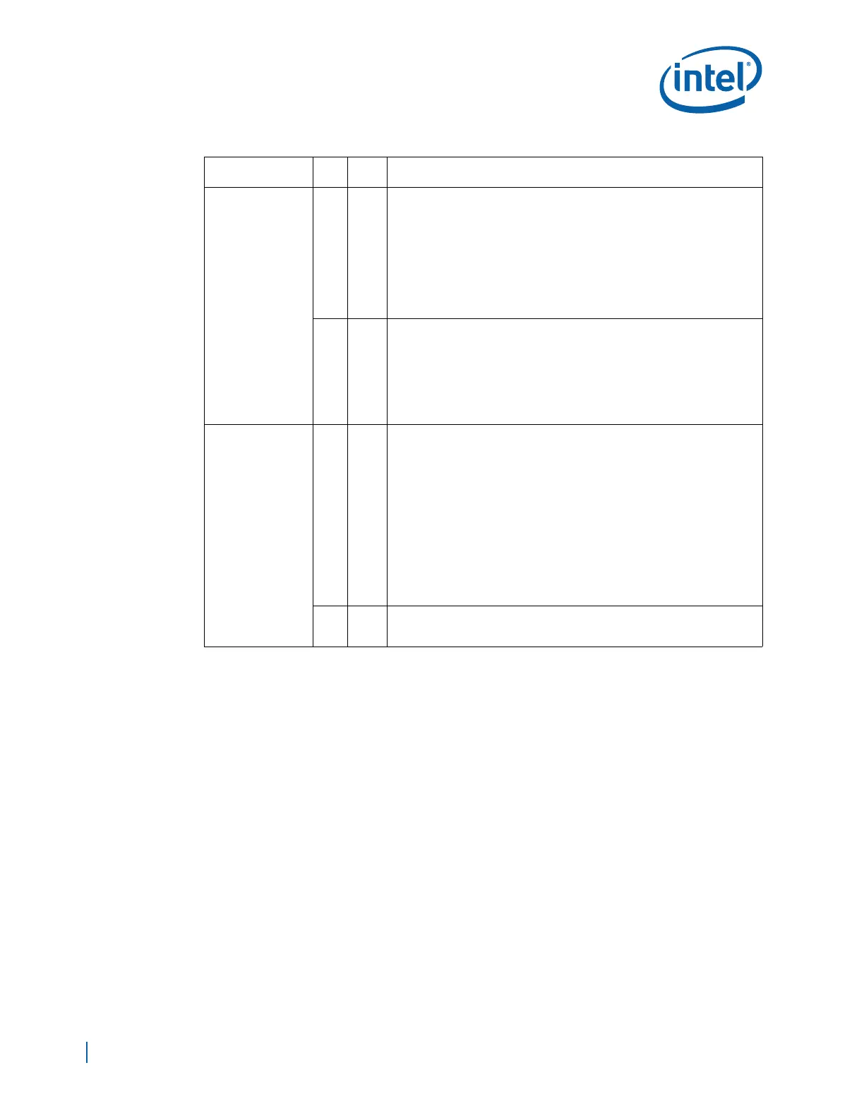
GBEn_TxDATA[3:0]
O4
RGMII Mode of Operation
• GBEn_TxDATA[3:0] signal name is GBEn_TxDATA[3:0] on the rising
edge of GBEn_TxCLK when GBEn_TxCTL is active
• GBEn_TxDATA[3:0] signal name is GBEn_TxDATA[7:4] on the falling
edge of GBEn_TxCLK when GBEn_TxCTL is active.
• Pull up GBE Port 0 Receive Data signals to EP80579 2.5V Standby
Voltage (VCCSUS25) using a 1.2KΩ ± 5% resistors.
• Pull up GBE Port 1&2 Receive Data signals to GBE 2.5V using a 1.2KΩ ±
5% resistors.
• Leave signals of any unused Port as no connect.
O2
RMII Mode of Operation:
• GBEn_TxDATA[1:0] signal name is GBEn_ TxDATA[1:0] on the rising
edge of the 50 MHz GBEn_REFCLK when GBEn_TxCTL is active.
• Pull up GBE Port 0 Receive Data signals to EP80579 3.3V Standby
Voltage (VCCGBEPSUS) using a 1.2KΩ ± 5% resistors.
• Pull up GBE Port 1&2 Receive Data signals to GBE 3.3V using a 1.2KΩ ±
5% resistors.
• Leave signals of any unused Port as no connect
GBEn_RxCLK
I1
RGMII Mode of Operation:
• The signal name is GBEn_RxCLK.
• This signal is the continuous receive clock and will be 125 MHz,
25 MHz, or 2.5 MHz +- 50ppm depending on data link speed. This
clock shall be derived at the PHY and supplied by the PHY to the MAC
from the received data stream.
— 125 MHz when operating at 1000Base-X speeds
— 25 MHz when operating at 100Base-X speeds
— 2.5 MHz when operating at 10Base-X speeds
• Pull up GBE Port 0 Receive Clock signal to EP80579 2.5V Standby
Voltage (VCCSUS25) using a 1.2KΩ ± 5% resistor.
• Pull up GBE Port 1&2 Receive Clock signals to GBE 2.5V using a 1.2KΩ
± 5% resistors.
• Pull-down all unused Receive Clock signals to GND using 10 KΩ resistors
I1
RMII Mode of Operation:
• GBEn_RxCLK should be connected to GND with a 10 KΩ pull-down
resistor when the interface is configured in this mode.
Table 80. GBEn Pin Table (Sheet 2 of 4)
GBEn Signal Name
Pin
Type
Pin
Count
Description

 Loading...


