Intel
®
EP80579 Integrated Processor Product Line—Schematics Checklist
Intel
®
EP80579 Integrated Processor Product Line
Platform Design Guide May 2010
291 Order Number: 320068-005US
GP27_IRQ39 I/O
• Input/Output configurable if
used as GPIO[27].
• Can be used as IRQ[39]
• No external pull-up required if used
in IRQ mode.
Note:
• Must be pulled high through a 10
KΩ resistor if not used.
• Resides in Suspend Power Well
GP28_IRQ30 I/O
• Input/Output configurable if
used as GPIO[28].
• Can be used as IRQ[30]
• No external pull-up required if used
in IRQ mode.
Note:
• Must be pulled high through a 10
KΩ resistor if not used.
• Resides in Suspend Power Well
GP29_SATA1GP I
• Input Only if used as GPIO[29]
• Can be used as SATA Port 1
Interlock switch Status Input
depending on the platform
•SATA1GP:
Interlock Switch Status Port1:
0 = Closed
1 = Open
• Must be pulled high through a 10
KΩ resistor if not used.
• Resides in Core Power Well
GP30_IRQ31 I
• Input only if used as GPIO[30].
• Can be used as IRQ[31]
• No external pull-up required if used
in IRQ mode.
Note:
• Must be pulled high through a 10
KΩ resistor if not used.
• Resides in Core Power Well
GP31_IRQ32 I
• Input only if used as GPIO[31].
• Can be used as IRQ[32]
• No external pull-up required if used
in IRQ mode.
Note:
• Must be pulled high through a 10
KΩ resistor if not used.
• Resides in Core Power Well
GP33_IRQ33 I/O
• Input/Output configurable if
used as GPIO[33].
• Can be strapped for SPI Boot-
up
• Can be used as IRQ[33]
• This pin, in conjuction with
GP17_IRQ25, can be strapped
to select the source of BIOS
during boot-up.
• Since GP17 and GP33 have
internal pull-ups, the default
bootup is set to FWH. GP17 and
GP33 should be strapped to
ground through 1KΩ pull-down
resistors to configure the boot
source to the SPI Flash.
• This signal can function as either
GPIO[33] or IRQ[33].
• 50KΩ internal pull-up
Boot BIOS Selection Strap: This strap
selects the source of the BIOS for
system boot.
EP80579 interprets GP17 & GP33
strappings as follows:
GP17 GP33 (Boot Options)
0 0 Boot BIOS from SPI
0 1 Reserved
1 0 Reserved
1 1 (Default) Boot BIOS from LPC
•See Table 74 for more details
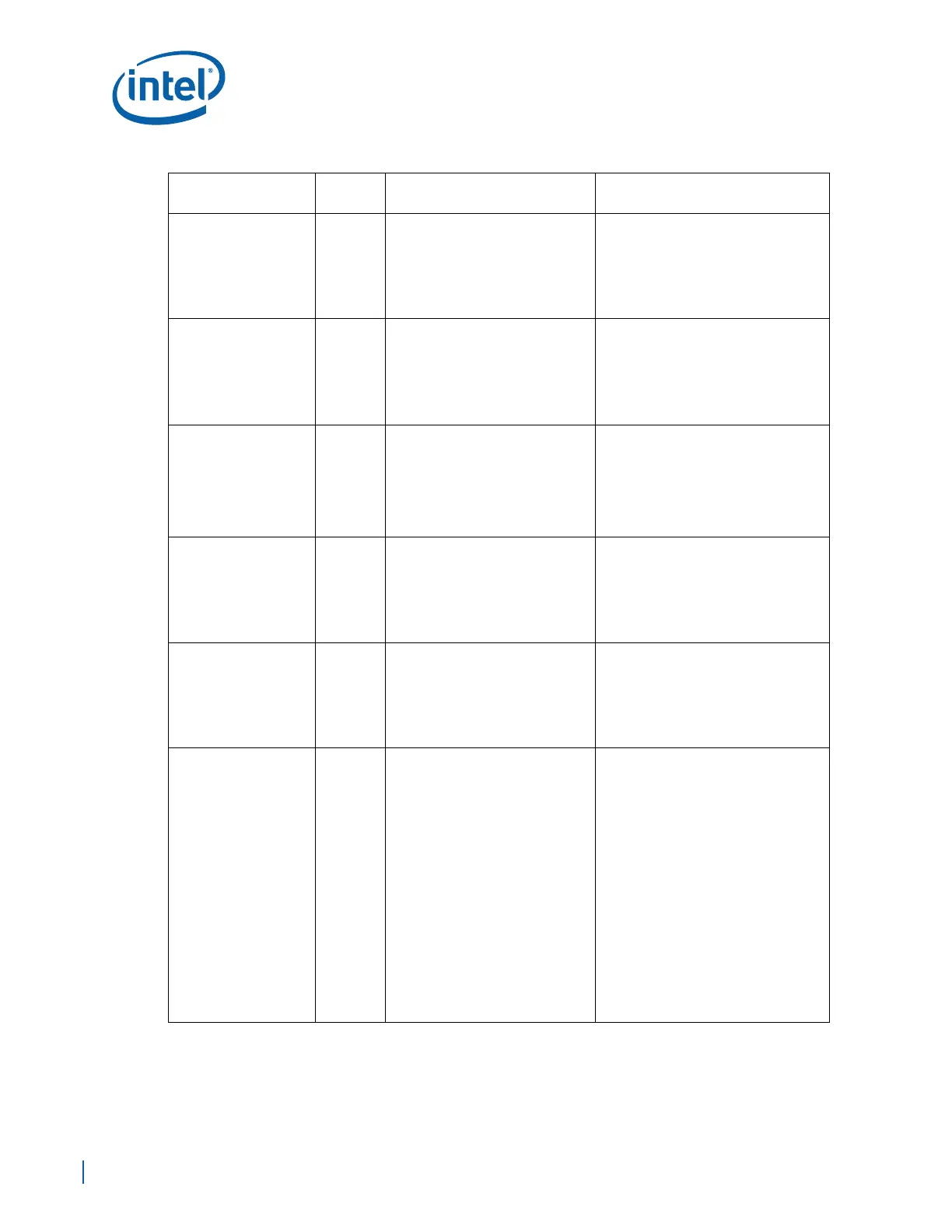
Table 100. Schematic Checklist (Sheet 8 of 26)
Checklist Items
I/O Type
(Default)
Recommendations Comments
 Loading...


