6 - 28 Module 5.2 - Mesh Data Extraction
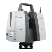
Figure 4
•
Define a fence around the incorrect triangles
via Edit | Modes | Polygonal Fence Mode
Edit | Modes | Polygonal Fence ModeEdit | Modes | Polygonal Fence Mode
Edit | Modes | Polygonal Fence Mode.
•
Select them via Selection | Select Fenced
Selection | Select FencedSelection | Select Fenced
Selection | Select Fenced.
•
All selected mesh triangles turn blue.
All triangles crossed by the fence
are selected.
Switching to a Top View before
placing the fence avoids
accidental selection of triangles in
the back or front.
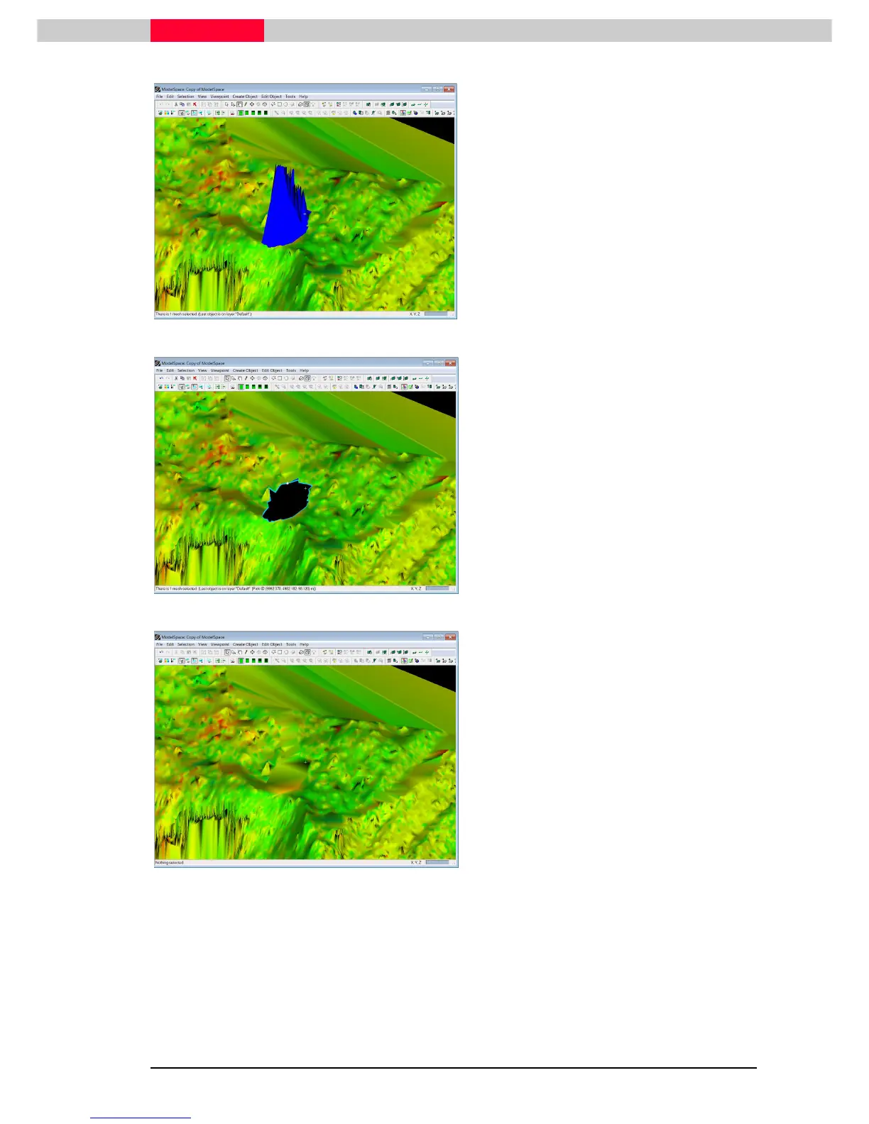
Figure 5
•
Select Tools | Mesh | Delete Selection
Tools | Mesh | Delete SelectionTools | Mesh | Delete Selection
Tools | Mesh | Delete Selection. This
deletes only the selected spikes.
Do not hit the delete key as this
will delete the entire mesh!
Alternatively, place a fence and
execute Edit | Fence |
Edit | Fence | Edit | Fence |
Edit | Fence | Delete
Delete Delete
Delete
Inside (Shift I)
Inside (Shift I)Inside (Shift I)
Inside (Shift I)
•
The newly created hole in the mesh now has
to be filled with interpolated data.
•
Click on the very edge on the hole. It is
selected when the surround appears in a light
blue colour.
Figure 6
•
Select Tools | Mesh | Fill selected Hole
Tools | Mesh | Fill selected HoleTools | Mesh | Fill selected Hole
Tools | Mesh | Fill selected Hole.
..
.
•
This now fills the hole with interpolated
triangles as seen in Figure 6.
Continue to edit the other two regions in the same manner.
Once accomplished bring the edited mesh back into its original ModelSpace.
 Loading...