17 - 18
3) In the Sections Manager, copy the Left, Right, Top, and Bottom values of the adjusted
section to the rest of the sections.
Adjust the value for a whole column by selecting the first in a column, then Shift
select the last in the column. Click again in the last of the column and enter the
desired value for the column then press Enter.
4) Step through the stations in the Section Manager by clicking
Section | Activate Next Section.
•
This command activates the selected section and displays the section within a
limit box (using the section's six dimensions). The viewpoint, a temporary
Reference Plane, and a temporary Cutplane are aligned to the current section.
•
Additionally, the datum and coordinate system origin and axes are temporarily
aligned to the section.
5) Click the Use Section’s Coordinate System button to toggle coordinate systems
between the local section’s coordinate system and the scene’s default coordinate system.
6) Select all sections listed in the
Sections Manager
, then click Section | Create Lines at
Section.
•
Create Lines is used to create lines based on a temporary TIN mesh created
from the points within each section.
•
Prior to this command, point clouds may be cleaned to produce the desired
resulting TIN mesh (i.e. at the median).
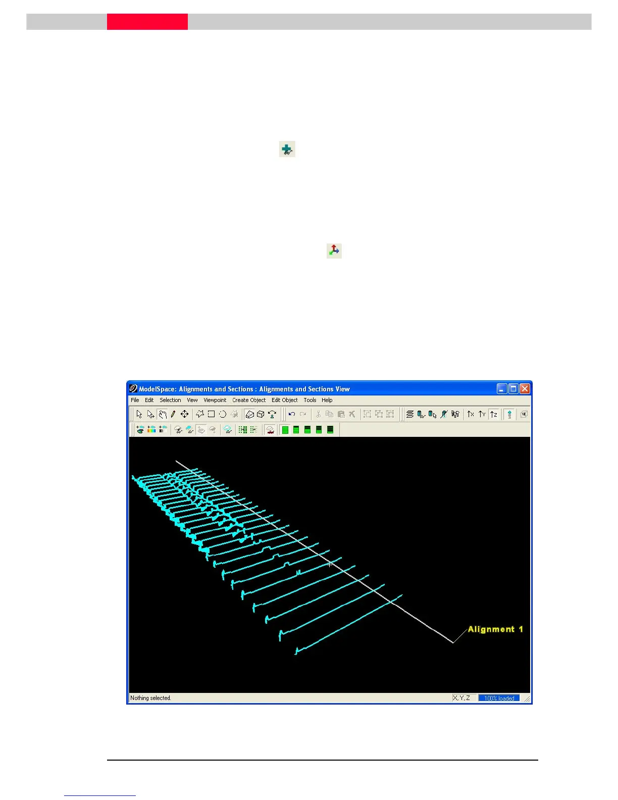
Figure 26
 Loading...