PowerPC e500 Core Family Reference Manual, Rev. 1
2-32 Freescale Semiconductor
Register Model
Table 2-16 describes the L1CSR0 fields.
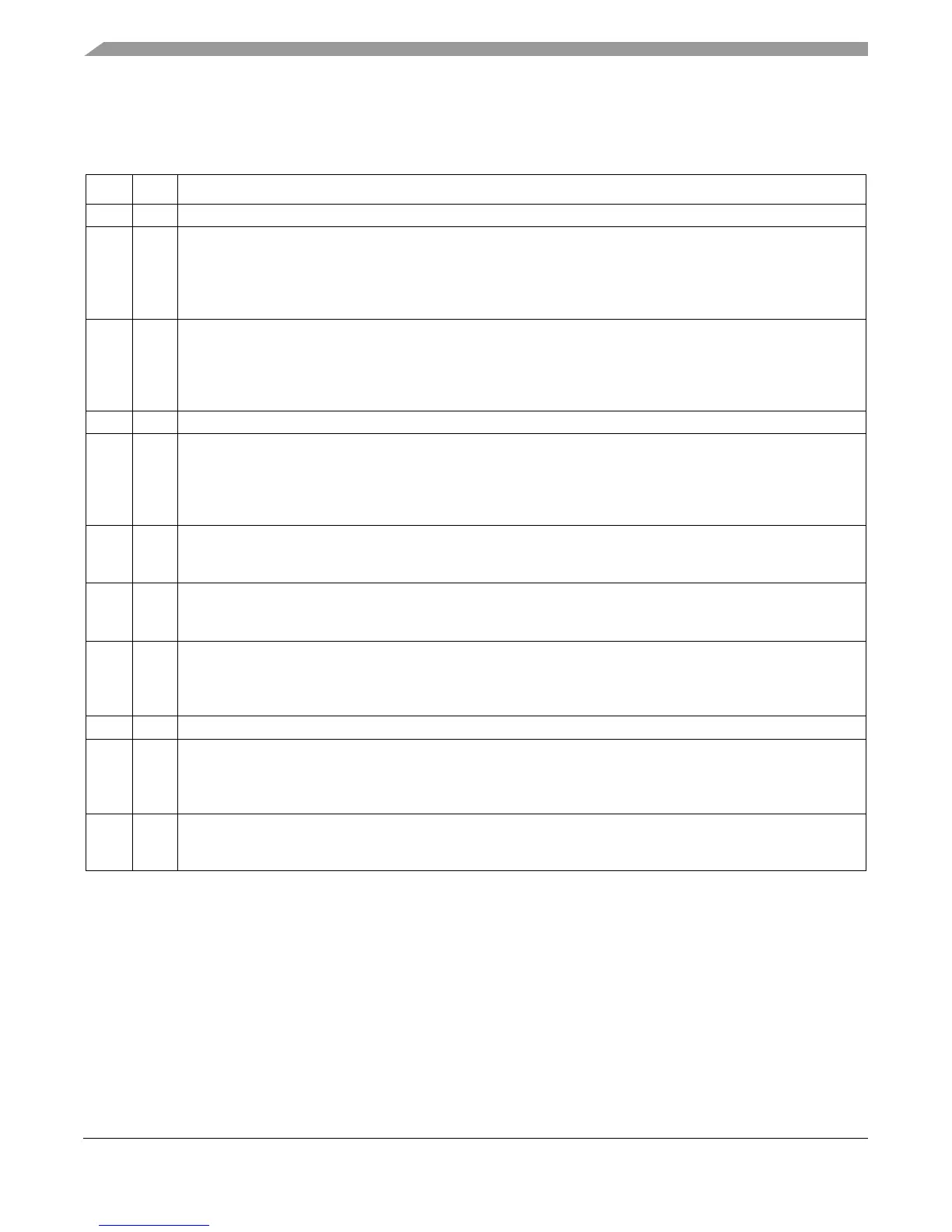
Table 2-16. L1CSR0 Field Descriptions
Bits Name Description
32–46 — Reserved, should be cleared.
47 CPE (Data) Cache parity enable. See Section 5.7.2, “Machine Check Interrupt.”
0 Parity checking of the cache disabled
1 Parity checking of the cache enabled
Note that if the programmer attempts to set L1CSR0[CPI] (using mtspr) without setting L1CSR0[CPE],
L1CSR0[CPI] will not be set (enforced by hardware).
48 CPI (Data) Parity error injection enable. See Section 5.7.2.2, “Cache Parity Error Injection.”
0 Parity error injection disabled
1 Parity error injection enabled. Cache parity must also be enabled (CPE = 1) when this bit is set.
Note that if the programmer attempts to set L1CSR0[CPI] (using mtspr) without setting L1CSR0[CPE],
L1CSR0[CPI] will not be set (enforced by hardware).
49–51 — Reserved, should be cleared.
52 CSLC (Data) Cache snoop lock clear. Sticky bit set by hardware if a dcbi snoop (either internally or externally
generated) invalidated a locked cache block. Note that the lock bit for that line is cleared whenever the line is
invalidated. This bit can be cleared only by software.
0 The cache has not encountered a dcbi snoop that invalidated a locked line.
1 The cache has encountered a dcbi snoop that invalidated a locked line.
53 CUL (Data) Cache unable to lock. Sticky bit set by hardware and cleared by writing 0 to this bit location.
0 Indicates a lock set instruction was effective in the cache
1 Indicates a lock set instruction was not effective in the cache
54 CLO (Data) Cache lock overflow. Sticky bit set by hardware and cleared by writing 0 to this bit location.
0 Indicates a lock overflow condition was not encountered in the cache
1 Indicates a lock overflow condition was encountered in the cache
55 CLFR (Data) Cache lock bits flash reset. Writing a 1 during a flash clear operation causes an undefined operation.
Writing a 0 during a flash clear operation is ignored. Clearing occurs regardless of the enable (CE) value.
0 Default
1 Hardware initiates a cache lock bits flash clear operation. CLFR resets to 0 when the operation completes.
56–61 — Reserved, should be cleared.
62 CFI (Data) Cache flash invalidate. (Invalidation occurs regardless of the enable (CE) value.)
0 No cache invalidate. Writing a 0 to CFI during an invalidation operation is ignored.
1 Cache invalidation operation. A cache invalidation operation is initiated by hardware. Once complete, CFI is
cleared. Writing a 1 during an invalidation causes an undefined operation.
63 CE (Data) Cache enable
0 The cache is neither accessed or updated.
1 Enables cache operation