PowerPC e500 Core Family Reference Manual, Rev. 1
2-24 Freescale Semiconductor
Register Model
2.8 Software-Use SPRs (SPRG0–SPRG7 and USPRG0)
The e500 implements the software-use SPRs (SPRG0–SPRG7 and USPRG0) as defined by the
Book E architecture. They have no defined functionality and are accessed as follows:
• SPRG0–SPRG2—These registers can be accessed only in supervisor mode.
• SPRG3—This register can be written only in supervisor mode. It is readable in supervisor
mode, but whether it can be read in user mode is implementation-dependent. It is readable
in user mode on the e500.
• SPRG4–SPRG7—These registers can be written only in supervisor mode. They are
readable in supervisor or user mode.
• USPRG0—This register can be accessed in supervisor or user mode.
2.9 Branch Target Buffer (BTB) Registers
SPRs are defined in the core complex for enabling the locking and unlocking of entries in the BTB.
These are called the branch buffer entry address register (BBEAR), the branch buffer target address
register (BBTAR), and branch unit control and status register (BUCSR). The user branch locking
enable bit, MSR[UBLE], is defined to allow user-mode programs to lock or unlock BTB entries.
See Section 3.9.1, “Branch Target Buffer (BTB) Locking Instructions,” for more information
about BTB locking. Section 2.5.1, “Machine State Register (MSR),” describes MSR bits that
support the BTB.
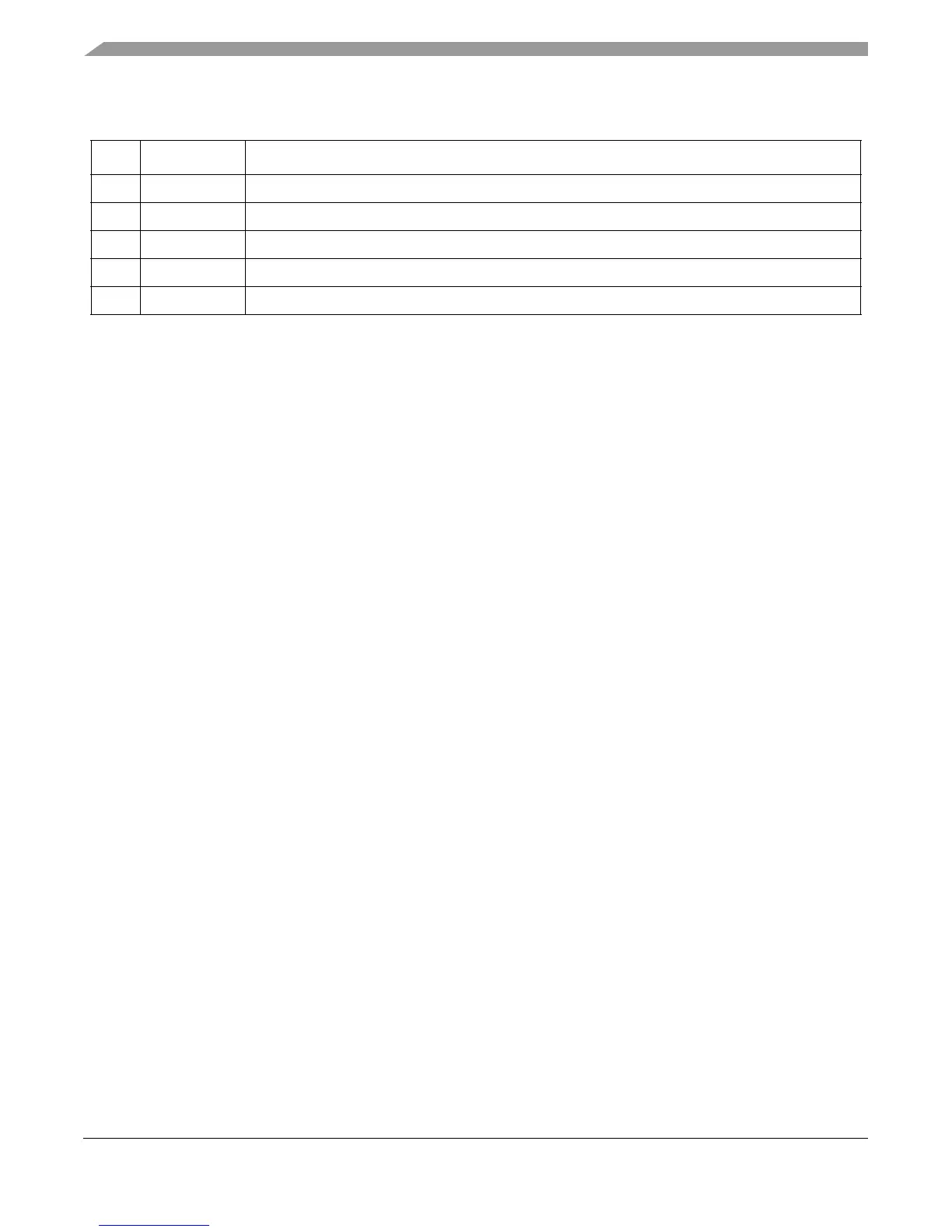
59 BUS_IBERR Bus instruction data bus error
60 BUS_RBERR Bus read data bus error
61 BUS_WBERR Bus write bus error
62 BUS_IPERR Bus instruction parity error
63 BUS_RPERR Bus read parity error
Table 2-10. MCSR Field Descriptions (continued)
Bit Name Description