PowerPC e500 Core Family Reference Manual, Rev. 1
Freescale Semiconductor 6-1
Chapter 6
Power Management
This chapter describes the power management facilities as they are defined by Book E and
implemented in devices that contain the e500 core. The scope of this chapter is limited to the
features of the core complex only. Additional power management capabilities associated with a
device that integrates this core (referenced as the integrated device throughout the chapter) are
documented separately.
6.1 Overview
A complete power management scheme for a system using the core complex requires the support
of logic in the integrated device. The core complex provides software a way to signal a need for
power management to the integrated device. It also provides a signal interface that the integrated
device can use to transition the core complex into its different power management states.
6.2 Power Management Signals
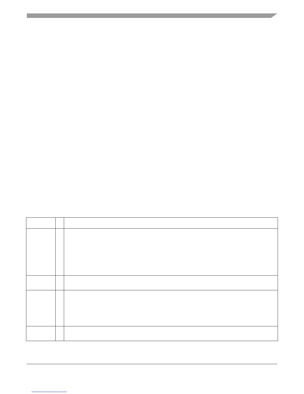
Table 6-1 summarizes the power management signals of the core complex.
Table 6-1. Power Management Signals of Core Complex
Signal I/O Description
halt
I Asserted by integrated device logic to initiate actions that cause the core complex to enter core-halted state,
as follows:
• Suspend instruction fetching.
• Complete all previously fetched instructions.
• When the instruction pipeline is empty, the core asserts the
halted
output.
The core clock continues running.
Negating
halt
returns the core complex to full-on state. If it is negated before the core complex has entered
core-halted state, the negation may not be recognized.
halted
O Asserted by the core complex when it reaches core-halted state. Indicates to the integrated device logic that
it is safe to power-down; that is, no data is lost on transition to the core-stopped state.
stop
I Asserted by integrated device logic to initiate the required actions that cause the core complex to go from
core-halted into core-stopped state (as described in Table 6-2 ).
Negating
stop
returns the core complex to core-halted state.
Once asserted,
stop
must not be negated until after the core complex has entered the core-stopped state;
otherwise the negation may not be recognized. For power management purposes,
stop
must be asserted only
while the core complex is in the core-halted state.
stopped
O Asserted by the core anytime the internal functional clocks of the core complex are stopped (for example after
integrated device logic asserts
stop
).