PowerPC e500 Core Family Reference Manual, Rev. 1
2-36 Freescale Semiconductor
Register Model
2.12.1 Process ID Registers (PID0–PID2)
The Book E architecture specifies that a process ID (PID) value be associated with each effective
address (instruction or data) generated by the processor. Book E defines one PID register that holds
the PID value for the current process. The e500 implements two additional PID registers, PID1
and PID2, shown in Figure 2-24. The number of PIDs implemented is indicated by the value of
MMUCFG[NPIDS]. PID values are used to construct virtual addresses for accessing memory. The
e500 implements only PID[54–63] for the process ID. Writing to PIDs requires synchronization,
as described in Section 2.16, “Synchronization Requirements for SPRs.”
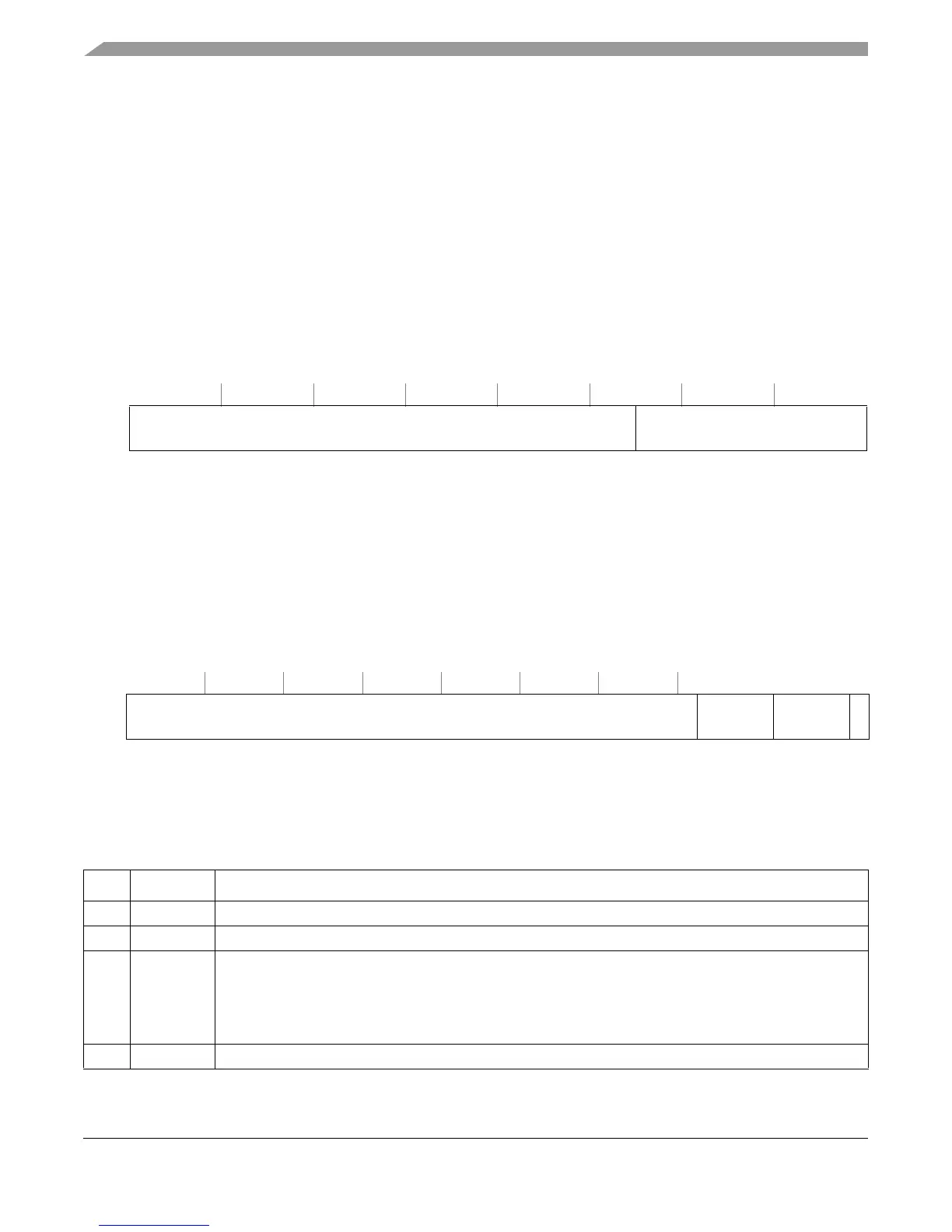
2.12.2 MMU Control and Status Register 0 (MMUCSR0)
The MMUCSR0 register (Figure 2-25) is used for general control of the L1 and L2 MMUs.
Writing to MMUCSR0 requires synchronization, as described in Section 2.16, “Synchronization
Requirements for SPRs.”
Table 2-20 describes the MMUCSR0 fields.
SPR
SPR
SPR
48 (PID0: PID in Book E);
633 (PID1: e500-specific);
634 (PID2: e500-specific)
Access: Supervisor-only
32 53 54 63
R
— Process ID
W
Reset All zeros
Figure 2-24. Process ID Registers (PID0–PID2)
SPR 1012 Access: Supervisor-only
32 58 59 60 61 62 63
R
— L2TLB0_FI L2TLB1_FI —
W
Reset All zeros
Figure 2-25. MMU Control and Status Register 0 (MMUCSR0)
Table 2-20. MMUCSR0 Field Descriptions
Bits Name Description
32–60 — Reserved, should be cleared.
61 L2TLB0_FI TLB0 flash invalidate (write 1 to invalidate)
62 L2TLB1_FI TLB1 flash invalidate (write 1 to invalidate)
0 No flash invalidate. Writing a 0 to this bit during an invalidation operation is ignored.
1 TLB1 invalidation operation. Hardware initiates a TLB1 invalidation operation. When this operation is
complete, this bit is cleared. Writing a 1 during an invalidation operation causes an undefined operation.
This invalidation typically takes 1 cycle.
63 — Reserved, should be cleared.