Register Model
PowerPC e500 Core Family Reference Manual, Rev. 1
Freescale Semiconductor 2-33
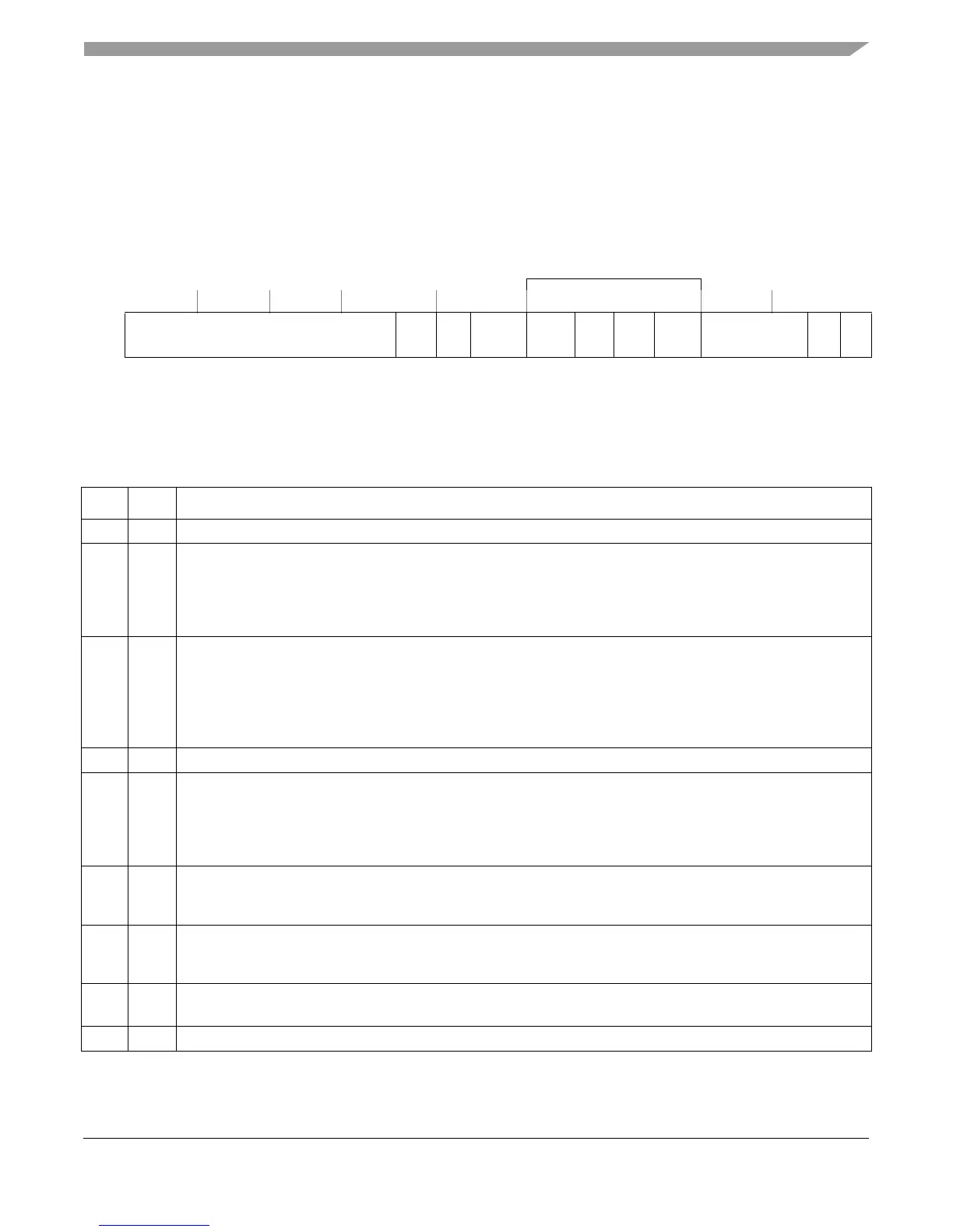
2.11.2 L1 Cache Control and Status Register 1 (L1CSR1)
The L1CSR1 register, defined as part of the EIS, is shown in Figure 2-21. It is used for general
control and status of the L1 instruction cache. Writing to L1CSR1 requires synchronization, as
described in Section 2.16, “Synchronization Requirements for SPRs.”
Table 2-17 describes the L1CSR1 fields.
SPR 1011 Access: Supervisor-only
Line Locking APU Bits
32 46 47 48 49 51 52 53 54 55 56 61 62 63
R
— ICPE ICPI — ICSLC ICUL ICLO ICLFR — ICFI ICE
W
Reset All zeros
Figure 2-21. L1 Cache Control and Status Register 1 (L1CSR1)
Table 2-17. L1CSR1 Field Descriptions
Bits Name Description
32–46 — Reserved, should be cleared.
47 ICPE Instruction cache parity enable. See Section 5.7.2, “Machine Check Interrupt.”
0 Parity checking of the instruction cache disabled
1 Parity checking of the instruction cache enabled
Note that if the programmer attempts to set L1CSR1[ICPI] (using mtspr) without setting L1CSR1[ICPE],
L1CSR1[ICPI] will not be set (enforced by hardware).
48 ICPI Instruction parity error injection enable. See Section 5.7.2.2, “Cache Parity Error Injection.”
0 Parity error injection into instruction cache disabled
1 Parity error injection into instruction cache enabled.Instruction cache parity must also be enabled (ICPE = 1)
when this bit is set.
Note that if the programmer attempts to set L1CSR1[ICPI] (using mtspr) without setting L1CSR1[ICPE],
L1CSR1[ICPI] will not be set (enforced by hardware).
49–51 — Reserved, should be cleared.
52 ICSLC Instruction cache snoop lock clear. Sticky bit set by hardware if an icbi snoop (either internally or externally
generated) invalidated a locked line in the instruction cache. Note that the lock bit for that line is cleared whenever
the line is invalidated. This bit can only be cleared by software.
0 The instruction cache has not encountered an icbi snoop that invalidated a locked line.
1 The instruction cache has encountered an icbi snoop that invalidated a locked line.
53 ICUL Instruction cache unable to lock. Sticky bit set by hardware and cleared by writing 0 to this bit location.
0 Indicates a lock set instruction was effective in the instruction cache
1 Indicates a lock set instruction was not effective in the instruction cache
54 ICLO Instruction cache lock overflow. Sticky bit set by hardware and cleared by writing 0 to this bit location.
0 Indicates a lock overflow condition was not encountered in the instruction cache
1 Indicates a lock overflow condition was encountered in the instruction cache
55 ICLFR Instruction cache lock bits flash reset. Writing 0 and then 1 flash clears the lock bit of all entries in the instruction
cache; clearing occurs independently from the value of the enable bit (ICE). ICLFR is always read as 0.
56–61 — Reserved, should be cleared.