PowerPC e500 Core Family Reference Manual, Rev. 1
2-34 Freescale Semiconductor
Register Model
2.11.3 L1 Cache Configuration Register 0 (L1CFG0)
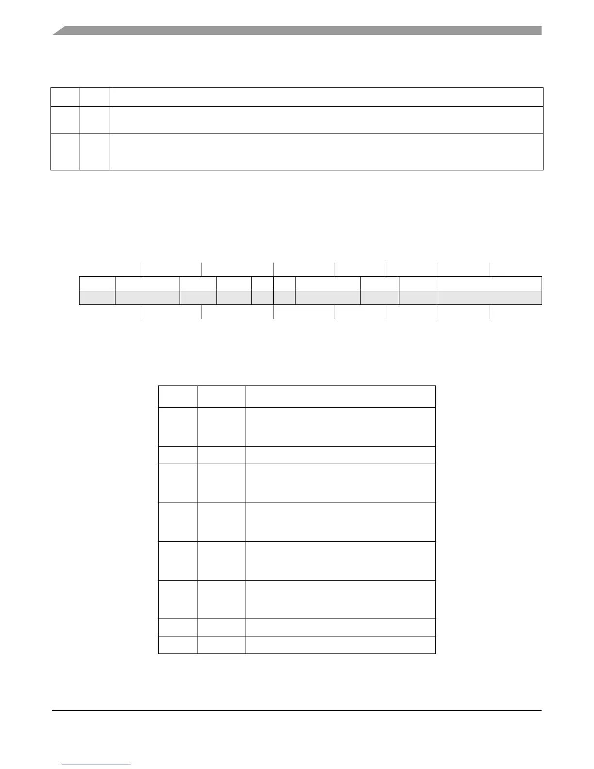
The L1CFG0 register, shown in Figure 2-22, is defined by the EIS to provide configuration
information for the L1 data cache supplied with this version of the e500 core complex.
Table 2-18 describes the L1CFG0 fields.
62 ICFI Instruction cache flash invalidate. Write to 0 and then write to 1 to flash clear the valid bit of all entries in the
instruction cache; operates independently from the value of the enable bit (ICE). ICFI is always read as 0.
63 ICE Instruction cache enable
0 The instruction cache is neither accessed or updated.
1 Enables instruction cache operation.
SPR 515 Access: Supervisor read-only
32 33 34 38 39 40 41 42 43 44 45 49 50 51 52 53 55 56 63
R CARCH — CBSIZE CREPL CLA CPA — CNWAY — CSIZE
W
Reset0 0 00000 0 0 0 1 1 1 0000011100000100000
Figure 2-22. L1 Cache Configuration Register 0 (L1CFG0)
Table 2-18. L1CFG0 Field Descriptions
Bits Name Description
32–33 CARCH Cache architecture
00 Harvard
01 Unified
34–38 — Reserved, should be cleared.
39–40 CBSIZE Cache block size
0 32 bytes
1 64 bytes
41–42 CREPL Cache replacement policy
0 True LRU
1 Pseudo LRU
43 CLA Cache locking APU available
0 Unavailable
1 Available
44 CPA Cache parity available
0 Unavailable
1 Available
45–49 — Reserved, should be cleared.
50–52 CNWAY Cache number of ways. 111 indicates eight ways
Table 2-17. L1CSR1 Field Descriptions (continued)
Bits Name Description