Register Model
PowerPC e500 Core Family Reference Manual, Rev. 1
Freescale Semiconductor 2-35
2.11.4 L1 Cache Configuration Register 1 (L1CFG1)
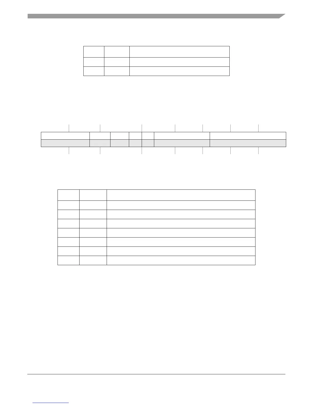
The L1CFG1 register, shown in Figure 2-23, provides configuration information for the particular
L1 instruction cache supplied with this version of the e500 core complex.
Table 2-19 describes the L1CFG1 fields.
2.12 MMU Registers
This section describes the following MMU registers and their fields:
• Process ID registers (PID0–PID2)
• MMU control and status register 0 (MMUCSR0)
• MMU configuration register (MMUCFG)
• TLB configuration registers (TLBnCFG)
• MMU assist registers (MAS0–MAS4, MAS6–MAS7)
53–55 — Reserved, should be cleared.
56–63 CSIZE Cache size. 0x20 indicates 32 Kbytes.
SPR 516 Access: Supervisor read-only
32 38 39 40 41 42 43 44 45 52 53 63
R — ICBSIZE ICREPL ICLA ICPA ICNWAY ICSIZE
W
Reset0000000 0 0 0 1 1 1 0000011100000100000
Figure 2-23. L1 Cache Configuration Register 1 (L1CFG1)
Table 2-19. L1CFG1 Field Descriptions
Bits Name Description
32–38 — Reserved, should be cleared.
39–40 ICBSIZ Instruction cache block size. 00 indicates block size of 32 bytes
41–42 ICREPL Instruction cache replacement policy. 01 indicates pseudo-LRU policy.
43 ICLA Instruction cache locking available. 1 indicates available.
44 ICPA Instruction cache parity available. 1 indicates available.
45–52 ICNWAY Instruction cache number of ways. 111 indicates eight ways.
53–63 ICSIZE Instruction cache size. 0x20 indicates 32 Kbytes.
Table 2-18. L1CFG0 Field Descriptions (continued)
Bits Name Description