PowerPC e500 Core Family Reference Manual, Rev. 1
4-4 Freescale Semiconductor
Execution Timing
4.2 Instruction Timing Overview
The e500 design minimizes the number of clock cycles it takes to fetch, decode, dispatch, issue,
and execute instructions and to make the results available for a subsequent instruction. To improve
throughput, the e500 implements pipelining, superscalar instruction issue, and multiple execution
units that operate independently and in parallel.
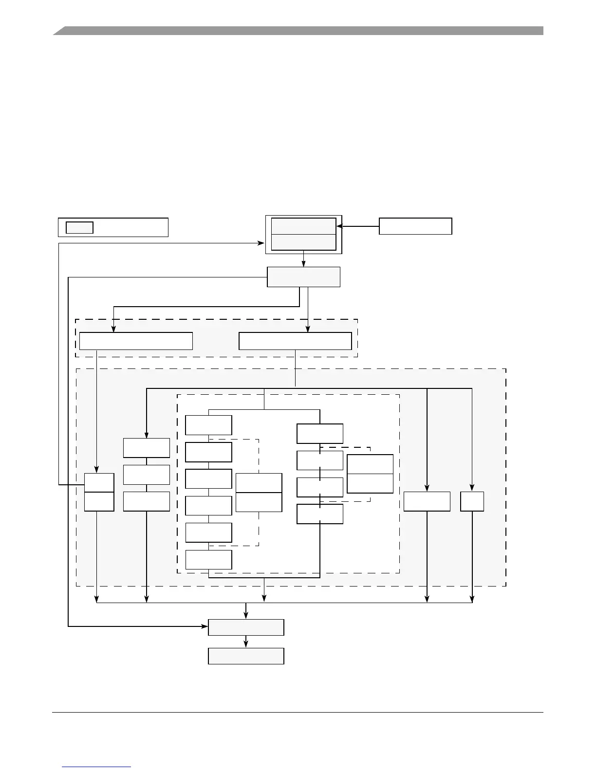
Figure 4-1 shows the path instructions take through the seven stages (shaded in the figure) of the
e500 master pipeline: two fetch stages, decode/dispatch, issue, execute, complete, and write-back
stages. The LSU and MU execution units are also multiple-stage pipelines.
Figure 4-1. Instruction Flow Pipeline Diagram Showing Pipeline Stages
Decode Stage
SU1
Maximum four-instruction
BU
BU
SU2
fetch per clock cycle
Fetch Stage 1
Fetch Stage 2
Completion Stage
Write-Back Stage
General Issue Queue (GIQ)
Execute Stage
Maximum two-instruction
completion per clock cycle
LSU Stage 1
Stage 2
Stage 3
At dispatch, instructions are deallocated from the
IQ and assigned sequential positions in the CQ.
Instruction Cache
Maximum two-instruction per cycle dispatch
to the issue queues. BIQ can accept one
per cycle; GIQ can accept at most two.
Issue Stage
Execute
Finish
Indicates stages
Branch Issue Queue (BIQ)
MU Stage 1
Stage 2
Stage 3
Stage 4
Divide Bypass
Stage 4
Stage 5
Stage 6
MU Stage 1
Stage 2
Stage 3
Stage 4
Divide Bypass
Postdivide
Divide
Double-Precision
Multiple Unit
Divide
Postdivide