PowerPC e500 Core Family Reference Manual, Rev. 1
1-24 Freescale Semiconductor
Core Complex Overview
1.9 Memory Management
The e500 core complex supports demand-paged virtual memory as well other memory
management schemes that depend on precise control of effective-to-physical address translation
and flexible memory protection as defined by Book E. The mapping mechanism consists of
software-managed TLBs that support variable-sized pages with per-page properties and
permissions. The following properties can be configured for each TLB:
• User-mode page execute access
• User-mode page read access
• User-mode page write access
• Supervisor-mode page execute access
• Supervisor-mode page read access
• Supervisor-mode page write access
• Write-through required (W)
• Caching inhibited (I)
• Memory coherency required (M)
• Guarded (G)
• Endianness (E)
• User-definable (U0–U3), a 4-bit implementation-specific field
The core complex employs a two-level memory management unit (MMU) architecture. There are
separate instruction and data level-1 (L1) MMUs backed up by a unified level-2 (L2) MMU,
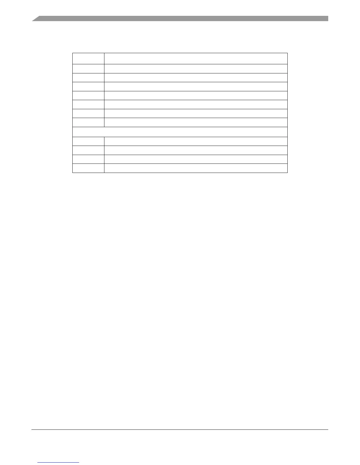
IVOR9 Auxiliary processor unavailable interrupt offset (not supported on the e500)
IVOR10 Decrementer interrupt offset
IVOR11 Fixed-interval timer interrupt offset
IVOR12 Watchdog timer interrupt offset
IVOR13 Data TLB error interrupt offset
IVOR14 Instruction TLB error interrupt offset
IVOR15 Debug interrupt offset
e500-Specific IVORs
IVOR32 SPE APU unavailable interrupt offset
IVOR33 SPE floating-point data exception interrupt offset
IVOR34 SPE floating-point round exception interrupt offset
IVOR35 Performance monitor
Table 1-7. Interrupt Vector Registers and Exception Conditions (continued)
Register Interrupt