Instruction Model
PowerPC e500 Core Family Reference Manual, Rev. 1
Freescale Semiconductor 3-41
See Section 3.3.1.8.1, “User-Level Cache Instructions,” for cache instructions that provide
user-level programs the ability to manage the on-chip caches.
3.3.2.2.2 Supervisor-Level TLB Management Instructions
The address translation mechanism is defined in terms of TLBs and page table entries (PTEs)
Book E processors use to locate the logical-to-physical address mapping for a particular access.
See Chapter 12, “Memory Management Units,” for more information about TLB operations.
Table 3-30 summarizes the operation of the TLB instructions in the e500.
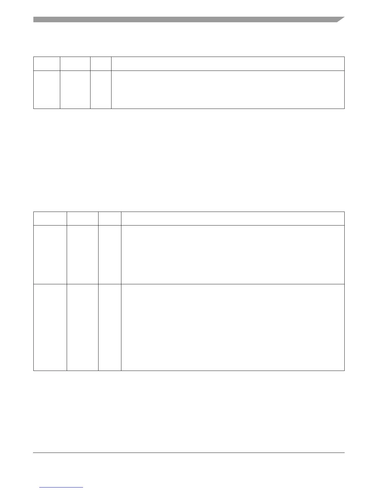
Table 3-29. Supervisor-Level Cache Management Instruction
Name Mnemonic Syntax Implementation Notes
Data
Cache
Block
Invalidate
dcbi rA,rB dcbi executes as described in Book E. The e500 core invalidates the cache block without
pushing it out to memory. See Section 3.3.1.8.1, “User-Level Cache Instructions.” In the e500,
dcbi cannot generate a cache-locking exception. The e500 broadcasts dcbi only if HID1[ABE]
is set. ABE must be set to allow management of external L2 caches (for implementations with
L2 caches) and other L1 caches in the system.
Table 3-30. TLB Management Instructions
Name Mnemonic Syntax Implementation Notes
TLB
Invalidate
Virtual
Address
Indexed
tlbivax rA, rB A TLB invalidate operation is performed whenever tlbivax is executed. tlbivax invalidates
any TLB entry that corresponds to the virtual address calculated by this instruction as long
as IPROT is not set; this includes invalidating TLB entries contained in TLBs on other
processors and devices in addition to the processor executing tlbivax. Thus, an invalidate
operation is broadcast throughout the coherent domain of the processor executing tlbivax.
For more information see Section 12.3, “Translation Lookaside Buffers (TLBs).”
On some implementations, HID1[ABE] must be set to allow management of external L2
caches (for implementations with L2 caches) as well as other L1 caches in the system.
TLB Read
Entry
tlbre — tlbre causes the contents of a single TLB entry to be extracted from the MMU and be placed
in the corresponding fields of the MMU assist (MAS) registers. The entry extracted is
specified by the TLBSEL, ESEL, and EPN fields of MAS0 and MAS2. The contents
extracted from the MMU are placed in MAS0–MAS3. Note that for the e500v2, if
HID0[EN_MAS7_UPDATE] = 1, MAS7 is also updated with the four highest-order bits of
physical address for the TLB entry. See Section 12.3, “Translation Lookaside Buffers
(TLBs).”
The RTL for the Freescale implementation of tlbre is as follows:
tlb_entry_id = MAS0(TLBSEL, ESEL | MAS2(EPN)
result = MMU(tlb_entry_id)
MAS0, MAS1, MAS2, MAS3, (and MAS7 if HID0[EN_MAS7_UPDATE] = 1) =
result