PowerPC e500 Core Family Reference Manual, Rev. 1
13-2 Freescale Semiconductor
Core Complex Bus (CCB)
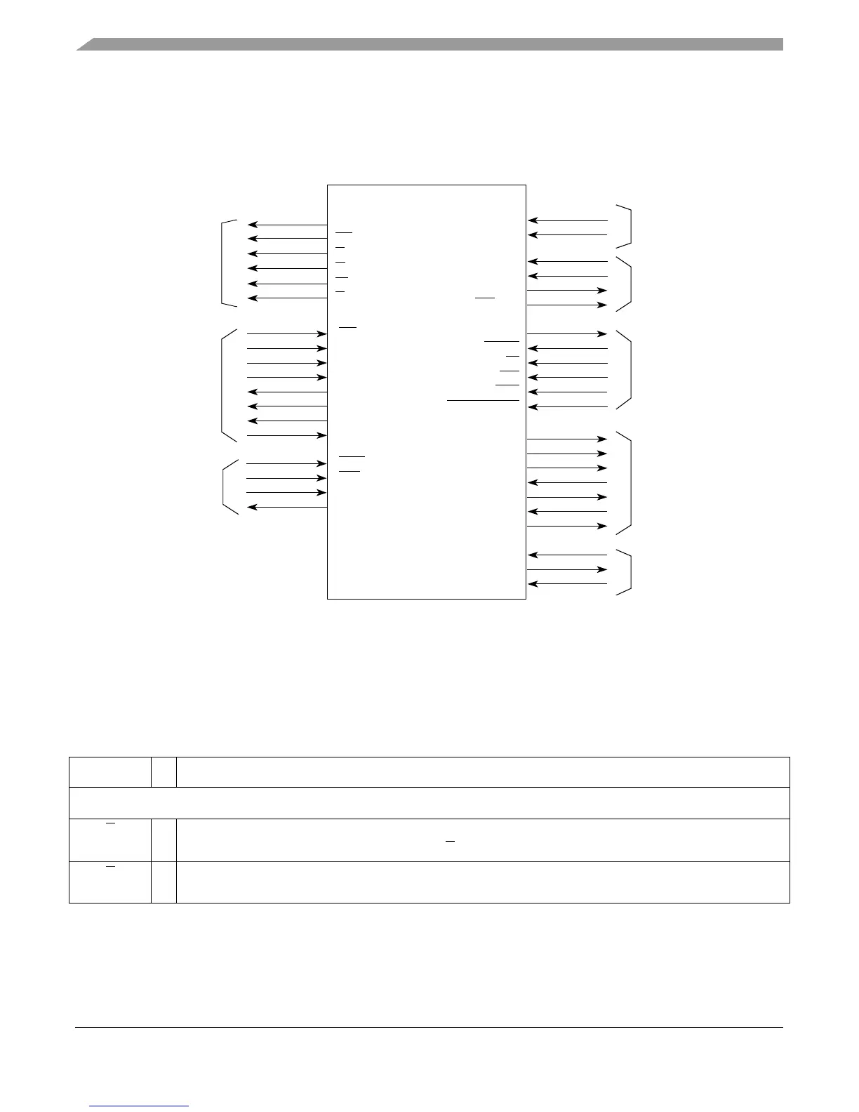
not attempt to characterize 60x bus behavior. Figure 13-1 shows the subset of CCB signals that
are discussed in this document.
Figure 13-1. CCB Interface Signals
13.2 Signal Summary
Table 13-1 briefly describes selected internal signals of the CCB.
Table 13-1. Summary of Selected Internal Signals
Signal I/O Comments, or Meaning when Asserted
Bus Signals: Master Address Bus
ci
O Cache inhibit. Normally reflected from the I bit of the WIMGE bits (regardless of whether the cache is enabled)
For burst writes and address-only transactions,
ci
is always negated.
cl
O Cache lock. Indicates L2 (level 2) cache lock status for the transaction; also asserted during a burst write for
dcbf
Master
Address Bus
tt
[0:4]
gbl
ci
Clocks
Time Base
cint
tbclk
doze
hreset_req
int
hreset
tben
nap
sleep
tbint
halt
halted
stop
wrs
[0:1]
stopped
Power
Management
External
Interrupts
pll_cfg
[0:5]
pm_event
pll_clk
pvr
[0:31]
svr
[0:31]
Miscellaneous
mcp
Selected CCB Signals
wt
cl
tck
trst
tms
tdo
tdi
tdo_ien
tlmsel
tap_en
clkout
JTAG and TAP
ckstp_out
ude
waitr
Test and Debug
ts
core_fault_in