PowerPC e500 Core Family Reference Manual, Rev. 1
8-4 Freescale Semiconductor
Debug Support
Table 8-3 describes the differences in DBCR0 and DBSR.
8.2.5 Hardware Facilities
The TAP (test access port) unit is a modified IEEE 1149.1 communication interface that facilitates
external test and debugging. However, because the core complex is a building block for further
integration, it does not contain IEEE 1149.1 standard boundary cells on its I/O periphery, so it
should not be considered IEEE 1149.1 compliant.
Private instructions allow an external debugger to freeze or halt the core complex, read and write
internal state, and resume normal execution.
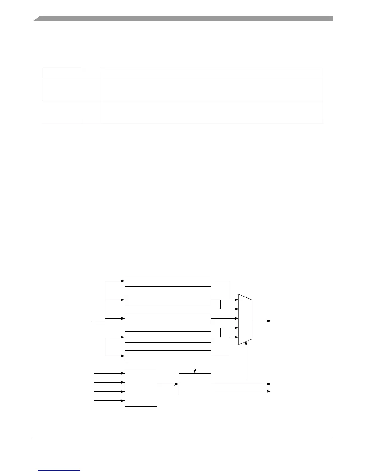
8.3 TAP Controller and Register Model
JTAG (joint test action group) is a serial protocol that specifies data flow though special registers
connected between test data in (TDI) and test data out (TDO). Figure 8-1 shows the TAP registers
implemented by the core complex. For more information, refer to IEEE Standard Test Access Port
and Boundary Scan Architecture IEEE STD 1149-1a-1993.
Figure 8-1. TAP Controller with Supported Registers
Table 8-3. DBCR0 and DBSR Field Differences
Bits Name Description
DBCR0[34–35] RST Reset
0
x
Default
1
x
A hard reset occurs if MSR[DE] and DBCR0[IDM] are set. Cleared on subsequent cycle.
DBSR[34–35] MRR Most recent reset. Undefined at power-up.
0
x
No hard reset occurred since this bit was last cleared by software.
1
x
The previous reset was a hard reset.
Service bus address register
Auxiliary data register (LSRL)
Service bus data register
Bypass register
TAP instruction register
TA P
Controller
tap_en
trst
tck
tms
TDO
MUX logic
tdi
tdo
tdo_en
tlmsel