PowerPC e500 Core Family Reference Manual, Rev. 1
11-26 Freescale Semiconductor
L1 Caches
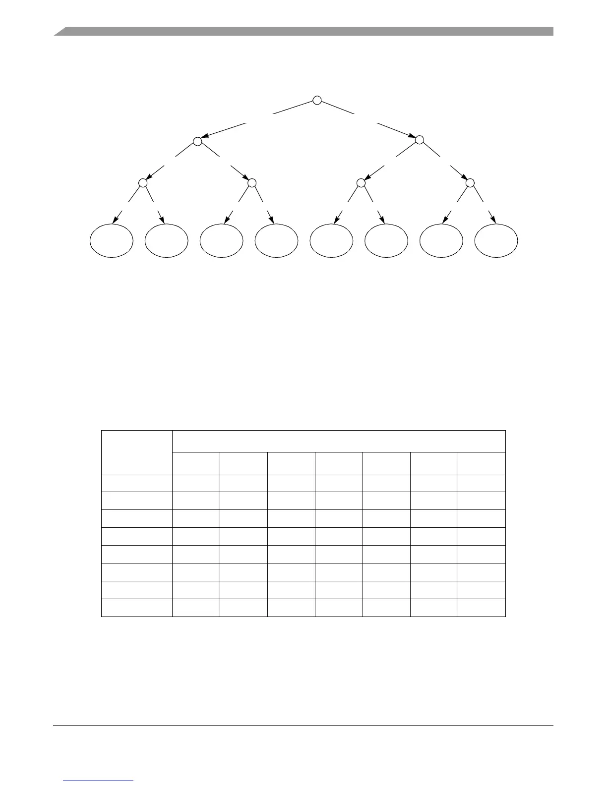
Figure 11-4 shows the decision tree used to generate the victim line in the PLRU algorithm.
Figure 11-4. PLRU Replacement Algorithm
During power-up or hard reset, the valid bits of the L1 caches are automatically cleared to point to
way L0 of each set.
11.6.2.2 PLRU Bit Updates
Except for snoop accesses, each time a cache block is accessed, it is tagged as the
most-recently-used way of the set. For every hit in the cache or when a new block is reloaded, the
PLRU bits for the set are updated using the rules specified in Table 11-9.
Note that only three PLRU bits are updated for any access.
Table 11-9. PLRU Bit Update Rules
Current Access
New State of the PLRU Bits
B0 B1 B2 B3 B4 B5 B6
L0 1 1 No change 1 No change No change No change
L1 1 1 No change 0 No change No change No change
L2 1 0 No change No change 1 No change No change
L3 1 0 No change No change 0 No change No change
L4 0 No change 1 No change No change 1 No change
L5 0 No change 1 No change No change 0 No change
L6 0 No change 0 No change No change No change 1
L7 0 No change 0 No change No change No change 0
Replace
L0
Replace
L1
Replace
L2
Replace
L3
Replace
L4
Replace
L5
Replace
L6
Replace
L7
B0 = 0
B4 = 0
B1 = 0 B1 = 1 B2 = 1B2 = 0
B0 = 1
B3 = 0 B3 = 1 B4 = 1 B5 = 0 B5 = 1 B6 = 0 B6 = 1