PowerPC e500 Core Family Reference Manual, Rev. 1
6-2 Freescale Semiconductor
Power Management
6.3 Core and Integrated Device Power Management States
The notion of nap, doze, and sleep modes (or states) pertains to the integrated device as a whole.
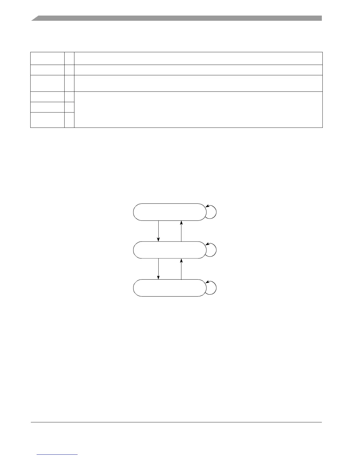
As shown in Figure 6-1, an integrated device may interpret the assertion of nap, doze, and sleep to
trigger actions that affect the device-level power state, which in turn may use the halt, stop, and
tben inputs to determine how the core transitions between the core-specific power states: full on,
core halted, and core stopped.
Figure 6-1. Core Power Management State Diagram
In addition to the power-management states, dynamic power management automatically stops
clocking individual internal functional units whenever they are idle. The integrated logic may
similarly stop clocking to idle device-level blocks.
tben
I Asserted by the integrated device logic to enable the time base.
tbint
O Asserted when a time base interrupt is signaled. This ordinarily prompts logic in the integrated device to bring
the core out of core-stopped state to service the interrupt.
doze
O Reflect the state of corresponding HID0[DOZE,NAP,SLEEP] bits (if MSR[WE] = 1); both must be set for the
respective output to assert. These signals do not affect the core’s power-down state, but indicate to the
integrated device of power management requests made by software.
Integrated device logic may use these signals to affect device-level power state, which in turn may affect the
core complex power state (signaled through the
halt
,
stop
, and
tben
).
nap
O
sleep
O
Table 6-1. Power Management Signals of Core Complex (continued)
Signal I/O Description
Core Halted
Core Stopped
halt
& ¬
stop
stop
¬
halthalt
¬
stopstop
&
halt
Full On ¬
halt
(Device doze state)
(Device nap or sleep state)