PowerPC e500 Core Family Reference Manual, Rev. 1
5-28 Freescale Semiconductor
Interrupts and Exceptions
When a data TLB error interrupt occurs, the processor suppresses execution of the instruction
causing the data TLB error exception.
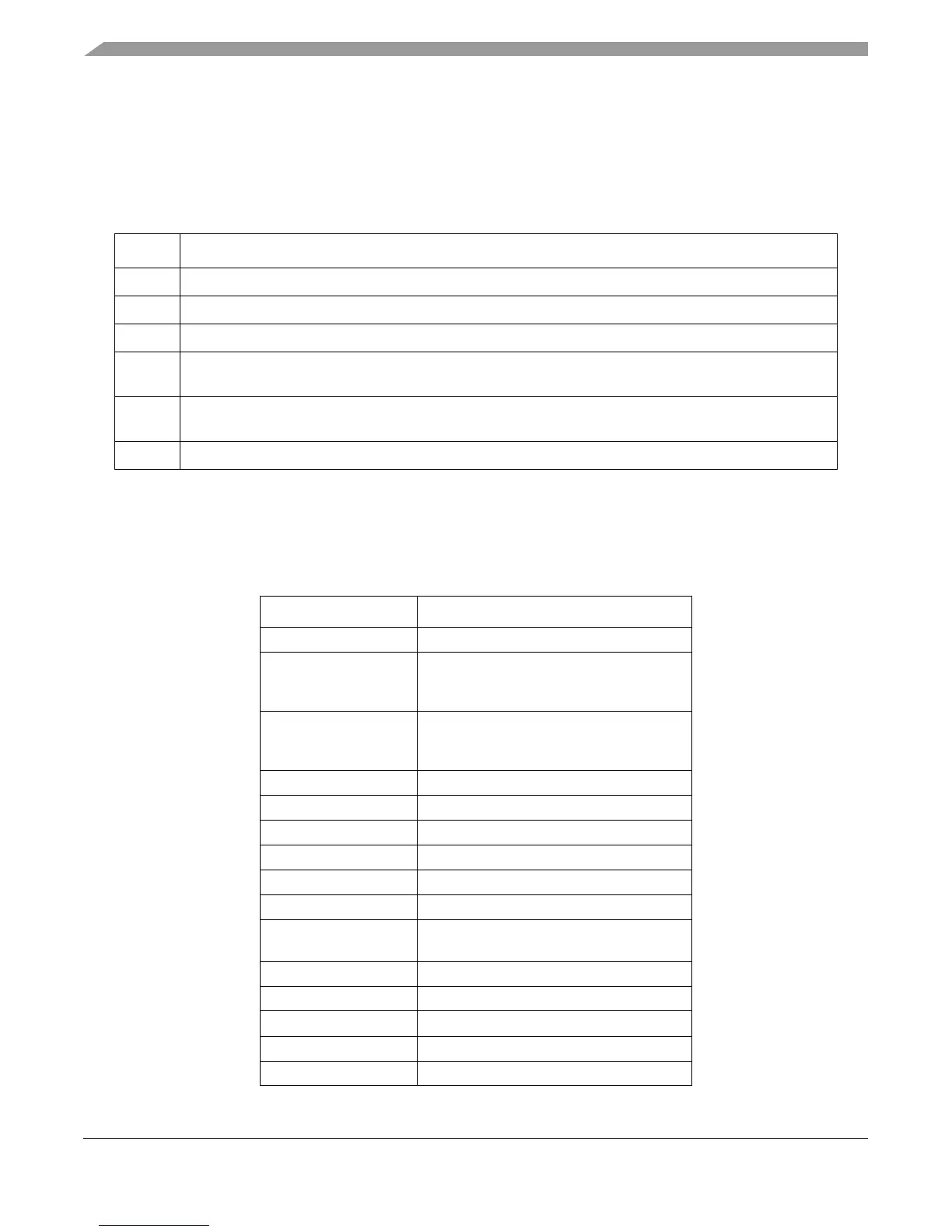
SRR0, SRR1, MSR, DEAR, and ESR are updated as shown in Table 5-24.
Table 5-25 shows MAS register settings for data and instruction TLB error interrupts as
implemented on the e500. The “Cache and MMU Background” chapter of the EREF describes
how these values are set as defined by the EIS.
Table 5-24. Data TLB Error Interrupt Register Settings
Register Setting
SRR0 Set to the effective address of the instruction causing the data TLB error interrupt.
SRR1 Set to the MSR contents at the time of the interrupt.
MSR CE, ME, and DE are unchanged. All other MSR bits are cleared.
DEAR Set to the EA of a byte that is both within the range of the bytes being accessed by the memory access or
cache management instruction and within the page whose access caused the data TLB error exception.
ESR ST Set if the instruction causing the interrupt is a store, dcbi, or dcbz instruction; otherwise cleared.
All other defined ESR bits are cleared.
MAS
n
See Tabl e 5 - 2 5.
Table 5-25. MMU Assist Register Field Updates for TLB Error Interrupts
MAS Register Bit/Field Value Loaded for Each Case
TLBSEL TLBSELD
ESEL if TLBSELD = 0:
TLB0[NV]
else, undefined
NV if TLBSELD = 0:
¬TLB0[NV]
else, undefined
V1
IPROT 0
TID[0–7] Value of PID register selected by TIDSELD
TS MSR[IS/DS]
TSIZE[0–3] TSIZED
EPN[32–51] EPN of access
X0, X1
W, I, M, G, E
X0D, X1D
WD, ID, MD, GD, ED
RPN[32–51] Zeros
PERMIS Zeros
TLBSELD —
TIDSELD[0–1] —
TSIZED[0–3] —