800-543-9038 USA 866-805-7089 CANADA 203-791-8396 LATIN AMERICA
3…
D
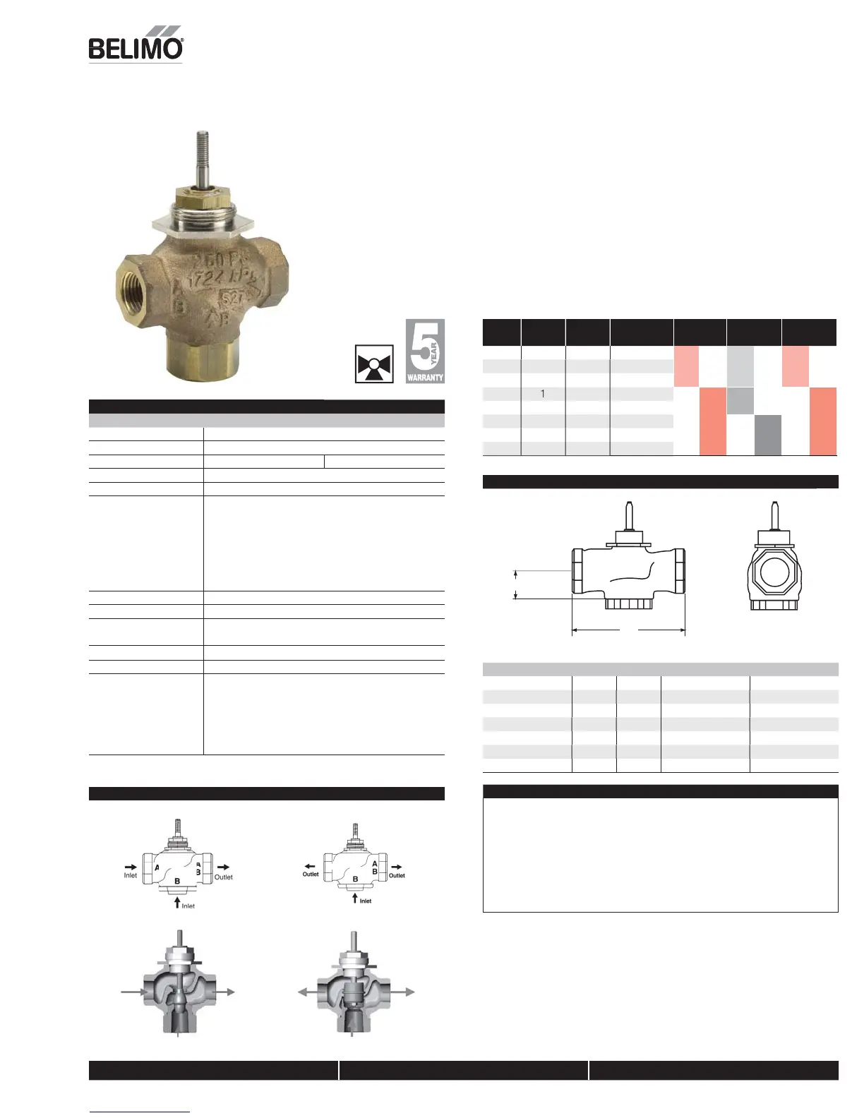
3-way Globe Valve, Bronze Trim
Applicatio
This valve is typically used in Air Handlin
Units on heatin
or coolin
coils and Fan Coil
Unit heating or cooling coils. Some other common applications include Unit Ventila-
tors, VAV Box reheat coils and bypass loops. This valve is suitable
or use in a hydronic
system with constant or variable fl ow.
3-way valves are available with mixing or diverting fl ow patterns
V
lv
N
min
l
iz
T
e
it
l
A
t
t
r
C
v
Inches DN [mm] 3-way NPT
Non-
Spring
Spring Electronic
Fail- Safe
2.2
1
14
LV
Series
LF
Series
LVK
Series
.
½
G315(D)
7.5
20 G320
D
4
2
G325
D
SV Series
NF
SVK Series
20 1¼ 32 G332
D
1
G340(D)
AF(X)
Series
41
0
350
40
0 G350
D
Dimensions
D078-3W
Valve Nominal Siz
Dimensions
Inches
mm
Valve Body Inches DN
mm
A
314
”
5
3.06
78
1.37
35
G315
D
½”
3.06
78
1.37
35
G320
D
¾” 2
3.62”
92
1.68”
43
325(D) 1” 2
4.62
117
1.56
40
G332
D
1¼” 32
4.62
117
1.62
41
G340
D
1½ 4
.37
137
1.62
41
350
D
50
6.12”
156
1.87”
48
Technical Data
G3 G3...D
ervice
hilled or hot water, 60% glycol
Flow characteristic
inear
A
ti
n
tem u
- o
en B to AB
tem u
- o
en B to AB
Sizes ½” to 2”
End fi ttin
NPT female end
Materials
Body
Seat
Stem
Plu
acking
Disc
bronze
bronze
tainless stee
brass
pring loaded TFE
ANSI class
NSI 250 (up to 400 psi below 150°F)
Leakage
NSI III
Media temperature
water
0°F to 250°F
-7°C to 120°C
Maximum
P* water
35 psi (241 kPa
Ran
eabilit
:
Valve weight
G314, G315(D
320
320D
325,
332(D
325D
340
D
,
350
D
l
lbs
.5 lb
.5 l
lb
4 l
*(50% or more open
G3...(D) 3-way Flow Patterns
G3 3-way Mixin
Valv
G3…D 3-way Divertin
Valv
A
Stem Up- Open B to AB
tem Up- Open B to AB
ote: Flow B to A travels through center of plug
as shown
.
Piping
The valves should be mounted in a weather-protected area in a location that is within
the ambient limits o
the actuator. Allow su
cient room
or valve with actuator and
for service. Please allow 12” for complete actuator/linka
e removal. The G2
S
and
G3
D
preferred mountin
position of the valve is with the valve stem vertical above
the valve body, for maximum life. However, the assemblies can be mounted with the
va
ve stem vert
ca
or
or
zonta
n re
at
on to t
e p
pe.
e actuators s
ou
never
e
mounted underneath the valve, as condensation can build up and result in a
ailure o
the actuators. Do not reverse
ow direction
N40021 - 03/13 - Subject to change. © Belimo Aircontrols (USA), Inc.


 To Next Page