800-543-9038 USA 866-805-7089 CANADA 203-791-8396 LATIN AMERICA / CARIBBEAN
2
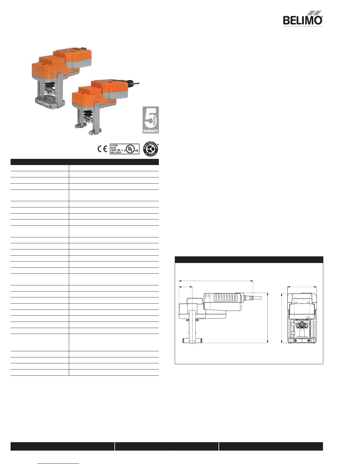
LVKB24-
R
Pro
ortional, Electronic Fail-Safe, Linear, 24 V, for 2 to 10 VDC or 4 to 20 mA
Technical Data
ower supp
24 VA
± 20% 50
60 Hz, 24 VD
± 10
Power consumption runnin
8.5 W
Power consumption holdin
2.5 W
Transformer sizin
21 VA
class 2 power source
lectrical connectio
3 ft, 18 GA plenum rated cable with 1/2
conduit connector protected NEMA 2
IP54
Overload protectio
electronic throughout full strok
Electrical protectio
actuators are double insulate
Contro
2-10 VDC
perating Range Y 2 to 10 VDC, 4 to 20 mA (default
Input impedance 100 k
for 2 to 10 VDC (0.1 mA), 500
fo
4 to 20 m
Feeback Output U 2 to 10 VD
tr
k
0.6" [15 mm]
Linear Force 112 lb
[500 N]
Direction of rotatio
reversible with switc
Position indication stroke indicator on bracke
anual override 4 mm hex crank (shipped with actuator
Running time motor 90 seconds (default), variable (90 to 150
seconds
Runnin
time
ail-sa
35 secon
s
Humidit
5 to 95% RH non condensin
Ambient temperatur
-22°F to +122°F
-30°C to +50°C
torage temperatur
-40°F to +176°F [-40°C to +80°C]
ousin
NEMA 2, IP54, UL enclosure type 2
Housin
material Aluminum die cast and plastic casin
Bridge Time 2 second delay be
ore
ail-sa
e activate
Initial Charge
t
2
n
ency listin
s
cULus acc. to UL 60730-1A/-2-14,
CAN/CSA E60730-1:02,
E acc. to 2004
108
E
and 2006
95
E
Noise leve
<55dB
A
Servicin
maintenance
re
Quality standard I
1
Wei
h
3.6 l
s
† Use flexible metal conduit. Push the Listed conduit fitting device over the actuator’s cable to butt agains
the enclosure.
crew in conduit connector. Jacket the actuators input wiring with Listed flexible conduit.
Properly terminate the conduit in a suitable junction box. Rated impulse Voltage 800V. Type of action 1
Control Pollution Degree 3
A
licatio
or fail-safe, proportional modulation of globe valves in HVAC steam and hydronic
ystems
ctuator sizing will be dictated by the valve size selection. All valve selections should
be done in accordance with the
low parameters and system speci
ications. The
actuator is mounted directly to the globe valve bonnet by means o
its universal clamp
and collar
The actuator operates in response to a 2 to 10 VDC, or with the addition of a 500
resistor, a 4 to 20 mA control input from an electronic controller or positioner. A 2 to 10
D
feedback signal is provided for position indication.
peratio
The actuator is not provided with and does not require any limit switches, but is
electronically protected a
ainst overload. The LV series provides 15 mm of downward
travel and a visual indicator indicates position of the actuator. When reachin
the valve
end position, the actuator automatically stops. The
ears can be manually disen
a
ed
t
a
utton on t
e actuator cover
The LVK… series actuators use a sensorless brushless DC motor. The ASIC inside
monitors and controls the actuator’s rotation and provides a di
ital rotation sensin
(DRS) function to prevent damage to the actuator in a stall condition. Power
consumption is reduced in holding mode
dd-on auxiliary switches are easily fastened directly onto the actuator body for
i
nalin
and switchin
functions. -SR and –MFT models will have an illuminated
green Adaption/Power button to reset and relearn the valve stroke as well as indicate
the actuator is powered. This feature allows the actuator to rescale itself based on the
actual travel
ail-Safe Indicatio
Green LED status indicator li
ht sequence:
On: operation ok, no fault
linking: fail-safe mechanism is active
Off: fault is detected or not in operation / capacitors chargin
Dimensions (Inches [mm])
3.9” [98]
1.8” [45]
8.2” [209]
6.6” [167]
6.7” [169]
P10401 - 01/13 - Subject to change. © Belimo Aircontrols (USA), Inc


 To Next Page