1 Bit Devices
27-4 SmartAXIS Touch User's Manual
1.2 Control Device Addresses
■ Input (I)
Inputs (I) are relays to receive input signals through the input terminals.
■ Output (Q)
Outputs (Q) are relays to send the processed results to the output terminals.
■ Remote Input (I)
Remote inputs (I) are devices to input the on/off state from external devices connected to remote I/O slaves to the
Touch.
■ Remote Output (Q)
Remote outputs (Q) are devices to output the on/off information from the Touch to external devices connected to
remote I/O slaves.
■ Timer (T)
Control device timers are bit unit devices that become 1 when the time is up.
■ Counter (C)
Control device counters are bit unit devices that become 1 when the count is up.
■ Shift registers (R)
Shift registers (R) are registers to shift the data bits according to pulse inputs.
■ Internal Relay (M)
Internal relays (M) are relays used in the Touch and cannot be outputted to the output terminals.
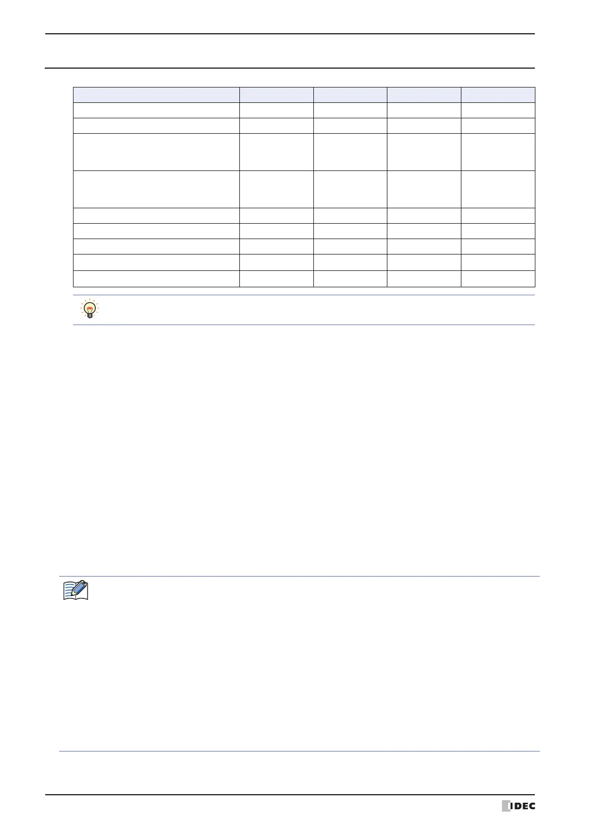
*1 The last digit of the device address is 0 to 7 in octal notation.
Internal Device Name Symbol R/W Address Range Base
Input I R 0 to 7 8
Output Q R/W 0 to 3 8
Remote Input I R
40 to 75
80 to 115
120 to 155
8
Remote Output Q R/W
40 to 61
80 to 101
120 to 141
8
Timer Bit T R 000 to 199 10
Counter Bit C R 000 to 199 10
Shift Register R R/W 0 to 127 10
Internal Relay M R/W 0 to 1277
10
*1
Special Internal Relay M R/W 8000 to 8177
10
*1
R/W stands for Read/Write. R/W enables reading and writing of values, whereas R enables reading only.
• Control devices must have a "#" before the device type only when the WindO/I-NV3 is used.
In addition, on the Device Monitor a "#" is displayed before the device type.
Example: When setting D100
WindO/I-NV3: #D100
WindLDR: D100
• Values can only be written from the HMI function to outputs (Q) while the ladder program or FBD program is
running.
• Do not simultaneously write values to the same control device using the HMI function and the control function.
• Operations in scripts of control function are as follows.
- Bit of Data register can be handled as a bit device.
- Calculations in which both bit and word devices are used are not allowed.
- Bit devices are always processed as bits, and values of those devices are 0(OFF) or 1(ON).