1 Touch
29-8 SmartAXIS Touch User's Manual
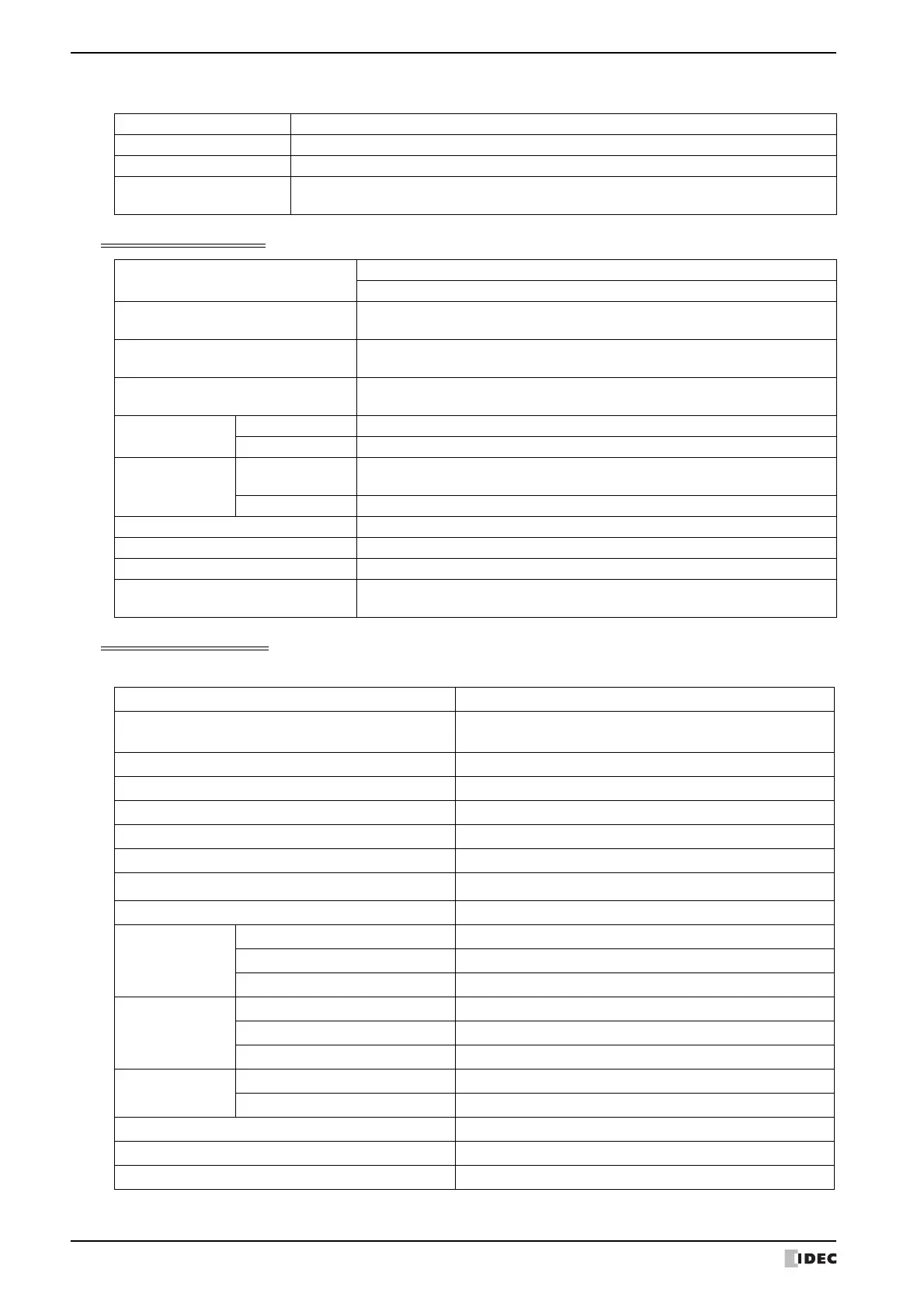
● Input Terminal Specifications
Digital Input Specifications
Analog Input Specifications
■ FT1A-*12RA
*1 This value may vary by device.
Input Points 8
Rated Input Voltage 24V DC
Input Voltage Range 0 to 28.8V DC
Effect of Improper
Input Connection
No damage.
(If any input exceeding the rated value is applied, permanent damage may be caused.)
Input Type
Sink (FT1A-*12RA/14SA)
Source (FT1A-*14KA)
Input Points
(Terminal No. /Common Line Name)
6 points in 1 common line
(I0 to I5/Power supply "-" terminal)
Rated Input Current
4.4mA (Sink Input)
5.2mA (Source Input)
Input Impedance
5.5k (Sink Input)
4.7k (Source Input)
Input System
Transfer Time
OFF → ON 2.5 s + filter value
ON → OFF 5 s + filter value
Isolation
Between input
terminals
Not isolated
Internal circuit Not isolated
Input Type Type1 (IEC61131-2)
External Load for I/O Interconnection Not needed
Signal Determination Method Static
Cable Length
(in compliance with EMC standards)
3m
Input Signal Type Voltage Input
Input Points
(Terminal No. /Common Line Name)
2 points in 1 common line
(I6, I7/internal -terminal, SG terminal for Port)
Input Range 0 to 10V DC
Rated Input Current 0.3mA
Input Impedance 78.0K
Digital Resolution 0 to 1,000 (850 steps)
Data Type Binary data: 0 to 1000
Input Value of LSB
*1
11.7mV
Type of Input Single-ended input
AD Conversion
Sample Duration Time 2 msec max.
Sample Repetition Time 2 msec max.
Total Input System Transfer Time 3 msec + filtering time + scan time
Input Error
Maximum Error at 25°C ±3.0% of full scale
Temperature Coefficient ±0.04% of full scale/°C
Maximum Error ±5.0% of full scale
General
Characteristics
Operating Mode Self-scan
Conversion Method type
Status Display Device Monitor screen (LCD)
Maximum Temporary Error during Electrical Noise Tests ±5.0% of full scale
Recommended Cable for Noise Immunity Twisted pair shielded cable