4 Special Functions
3-70 SmartAXIS Touch User's Manual
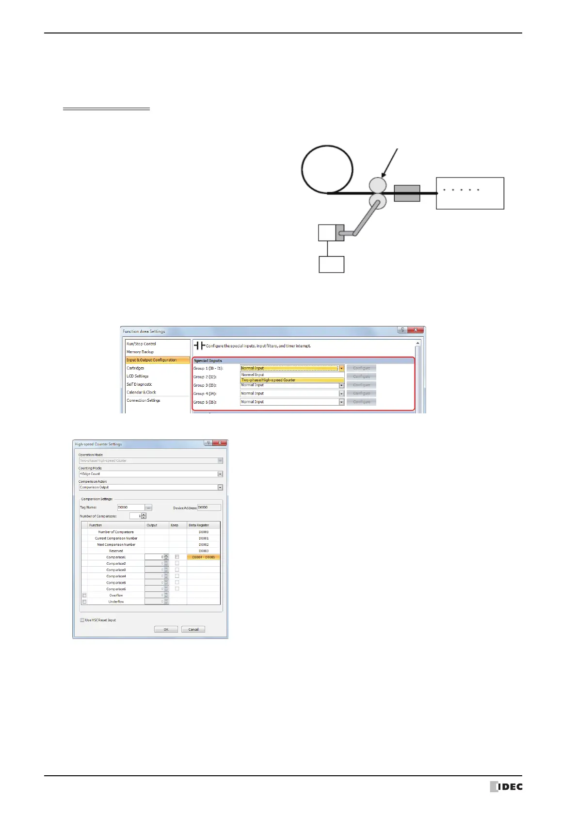
● Example 2
Using the two-phase high-speed counter, the pulses from a rotary encoder are input to the Touch and a continuous
workpiece is marked at a regular interval.
Application description
Select Two-phase High-speed Counter for Group 1 in the Input & Output Configuration group on Function
Area Settings tab.
In High-speed Counter Settings, configure the settings as follows.
• The rotary encoder pulses are input to input I0. A
continuous sheet of paper is marked (holes are
punched) at a regular interval (every 2,700
pulses).
• The rotary encoder is directly connected to the
paper feed roller, and output pulses are counted
by the high-speed counter and controlled.
• The cycle time is the time to count 2,700 pulses.
When the hole punch time is 0.5 seconds, the
operation condition is 2,700 pulse count time >
0.5 seconds.
External input : Group 1 (I0 to I1)
Operation Mode : Two-phase High-speed Counter
Counting Mode : 4 Edge Count
Comparison Action : Comparison Output
Comparison Settings
Tag Name/Device Address : D0000 (data register)
Number of Comparisons : 1
Comparison output : Q2 (external output when matched)
Comparison1 (D0004) : 0 (upper word)
Comparison1 (D0005) : 2,700 (lower word)
Keep : Cleared
Reset value (D8054) : 0 (upper word)
Reset value (D8055) : 0 (lower word)
Overflow : Cleared
Underflow : Cleared
Use HSC Reset Input : Cleared
Paper roll
Paper feed roller
Perforator
Rotary encoder
Tou ch