3 Pie Chart
10-44 SmartAXIS Touch User’s Manual
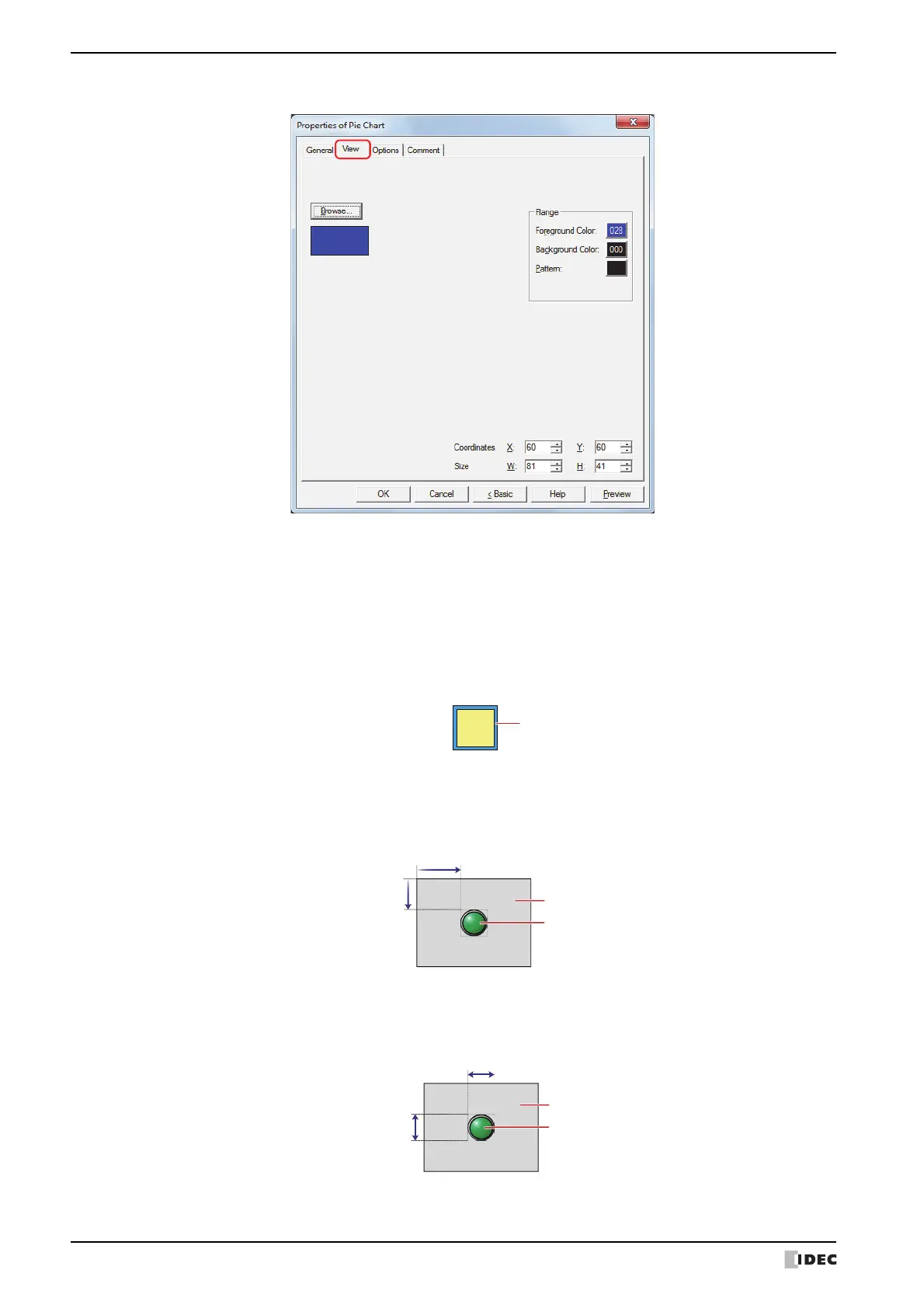
● View Tab
■ Browse
Select the type of graphic to be used to represent the part from the list of graphics. Click this button to display the
View Browser.
■ Flange
■ Coordinates
■ Size
Foreground Color, Background Color:
Selects the foreground and background colors of the flange (color: 256 colors, monochrome:
8 shades).
Click the Color button to display the Color Palette. Select a color from the Color Palette.
Pattern: Selects a pattern for the flange.
Click the Pattern button to open the Pattern Palette. Select a pattern from the Pattern Palette.
X, Y: Sets the display position of parts using coordinates.
The X and Y coordinates of parts are defined relative to an origin at the top-left corner of the screen.
X: 0 to (Base Screen horizontal size - 1)
Y: 0 to (Base Screen vertical size - 1)
W, H: Sets width and height to define the size of parts.
W: 5 to (Base Screen horizontal size)
H: 5 to (Base Screen vertical size)