3 Alarm Log Settings Dialog Box
13-14 SmartAXIS Touch User’s Manual
■ Monitoring Period (x 100 msec)
Specifies the period to write the state of the monitored device to the Touch (6 to 500 (100 milliseconds units)).
■ Monitor Number of Active Alarms
Select this check box to count the number of active alarms.
■ Monitor How Many Times Each Alarm has occurred
Select this check box to count the number of alarms that has occurred per channel.
■ Clear Log Data for Recovered Alarms
Select this check box to delete recovered data out of the saved Alarm Log data.
■ Monitor the State of Each Alarm
Select this check box to check the alarm state per channel.
The following values are written to the bits depending on the alarm state.
(Destination Device):
Specifies a word device to write the number of active alarms.
For the device address configuration procedure, refer to Chapter 2 “5.1 Device Address Settings”
on page 2-62.
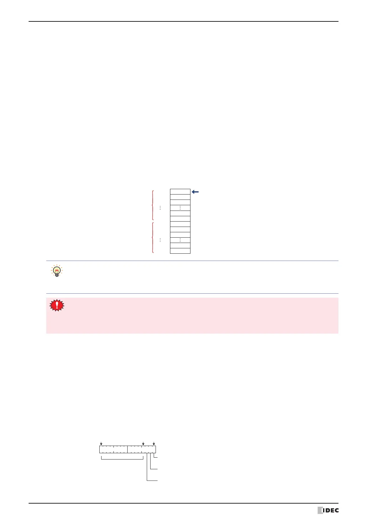
(Top Device): Specifies a word device to write the number of alarms that has occurred. Number of blocks x 16
(number of channels) addresses are used starting from the set device address.
For the device address configuration procedure, refer to Chapter 2 “5.1 Device Address Settings”
on page 2-62.
Example: When the number of blocks is 2 and LKR100 is specified as the starting device
The number of alarms that has occurred for channel number 1-0 is saved in LKR100.
The number of alarms that has occurred for channel 1-1 is saved in LKR101, and this
pattern continues up to LKR131 where the number of alarms that has occurred for
channel number 2-15 is saved.
Starting device
Block 1
16 channels
Block 2
16 channels
Channel No.
LKR100
LKR101
LKR102
LKR114
LKR115
LKR116
LKR117
LKR118
LKR130
LKR131
1-0
1-1
1-2
1-14
1-15
2-0
2-1
2-2
2-14
2-15
• If you specify HMI Keep Registers (LKR) as the destination word device, the number of alarms that has
occurred is retained even when the Touch power is turned off.
• The amount of Alarm Log data saved in the data storage area with the Alarm Log function is stored in
HMI Special Data Register LSD57.
• To monitor the number of alarms that has occurred, number of blocks x 16 (number of channels) devices
are required from the set starting device. If the destination device does not exist, “Device range error”
occurs on the Touch.
• If the values of devices that are counting the number of alarms that has occurred are overwritten by
another process, the alarms cannot be accurately counted.
(Trigger Device): Specifies the bit device or bit of the word device to serve as condition to delete data. The recovered
data is deleted when the value of the configured device changes from 0 to 1. For the device address
configuration procedure, refer to Chapter 2 “5.1 Device Address Settings” on page 2-62.
(Top Device): Specifies a word device to write the alarm state. Number of blocks x 16 (number of channels)
addresses are used starting from the set device address.
For the device address configuration procedure, refer to Chapter 2 “5.1 Device Address Settings”
on page 2-62.
Bit 15 Bit 0
Bit 3
0: Before alarm/after recovery
1: After alarm
0: Second and later alarm (Alarm that has occurred again while an alarm is active)
1: First alarm (First alarm that occurred)
0: After confirm
1: Before confirm
Reserved