3 Alarm Log Settings Dialog Box
13-16 SmartAXIS Touch User’s Manual
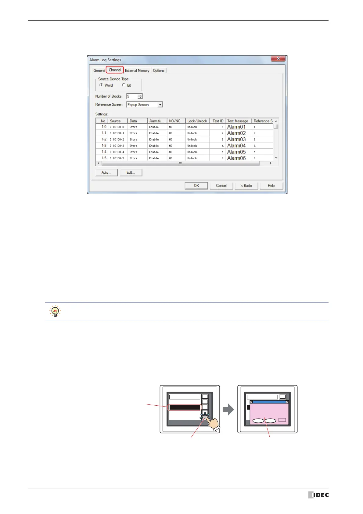
● Channel Tab
The Channel tab is used to configure the devices to monitor and the alarm detection condition.
■ Source Device Type
Selects the type of device to monitor.
■ Number of Blocks
Configures the Alarm Log data in block units. The number of blocks that can be set varies based on the Source
Device Type setting and the Touch model.
■ Reference Screen
Select the type of reference screen from the following items.
Base Screen, Popup Screen, Not Use
The reference screen is displayed when a message is selected on the Alarm List Display or the Alarm Log Display and
the key button Ref. is pressed. It is the Base Screen or Popup Screen associated with each channel.
Word: Uses a word device. Devices are configured per block.
Bit: Uses a bit device. Devices are configured per channel.
Word: 0 to 128
Bit: 0 to 8
One block is composed of 16 channels. One device can be monitored for each channel. The maximum
number of devices that can be monitored is 16 for each block.
Time
09:15 Motor fault
Message
10:02 Pump1 fault
REV
Up
Dwn
Del
Ref.
10:28 High pressure
13:02 Pump 1 fault
Time
09:15 Motor fault
Message
10:02 Pump1 fault
REV
Up
Dwn
Del
Ref.
10:28 High pressure
13:02 Pump 1 fault
Pump 1 faultPump 1 fault
Pump 1 output low
Stop Start
Press Stop, check the air,
then press Start.
Air Press.
kg/m
2
0000
Key button Ref.
1. Select a message displayed
on the Alarm List Display
or the Alarm Log Display
Reference screen
2. Press the key button Ref.
The reference screen opens