Intel
®
EP80579 Integrated Processor Product Line May 2010
Order Number: 320068-005US 273
Layout Checklist—Intel
®
EP80579 Integrated Processor Product Line
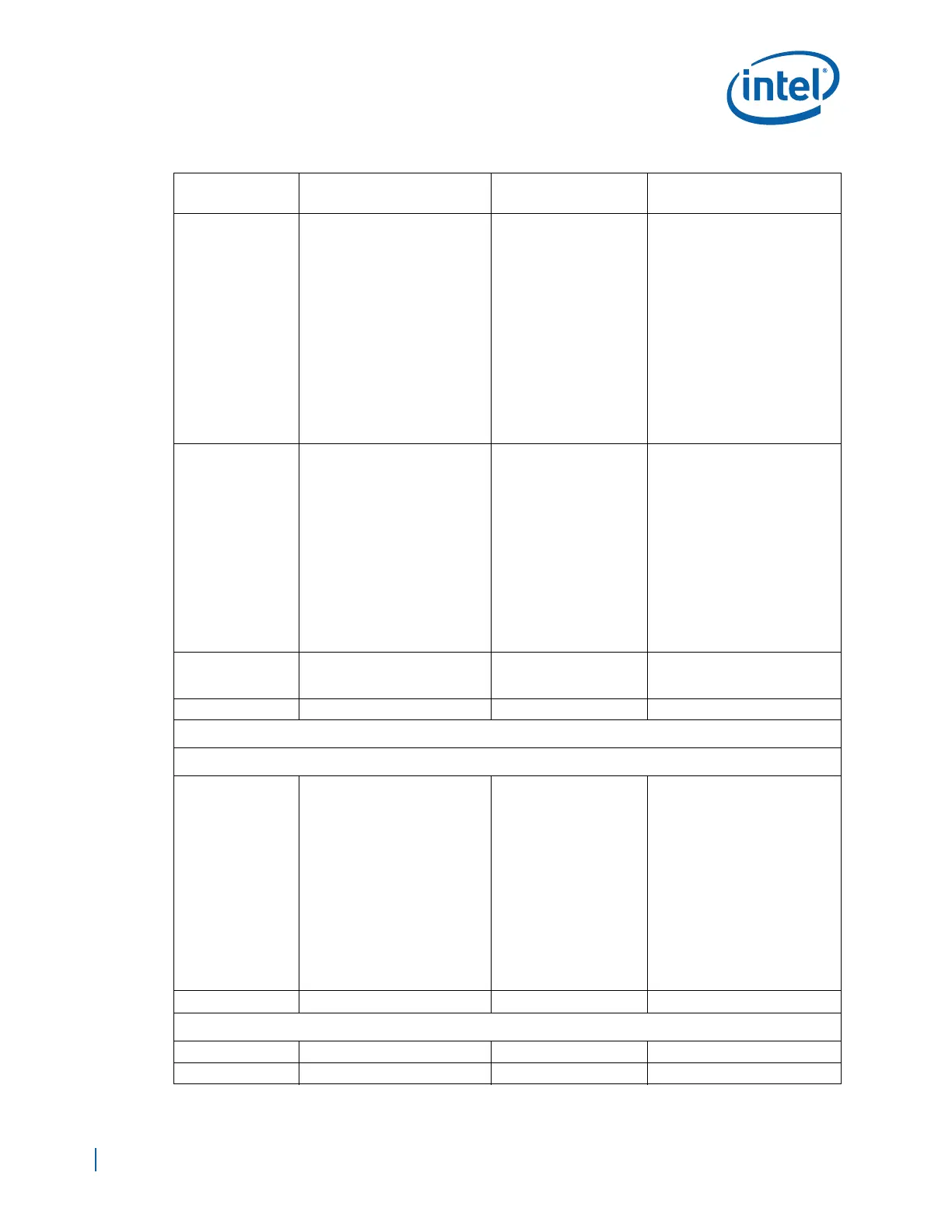
PEA0_Rp[7:0],
PEA0_Rn[7:0]
Zdiff = 90
Ω +/- 10%
Trace Width:
Brakeout Trace Width 4 mils
Microstrip: 4.75 mils
Stripline: 4.5 mils (L3/L8)
Airgap Spacing:
Brakeout spacing Min=4mils
Microstrip: 5.25 mils
Stripline: 5.5 mils
Spacing between Pairs, the
greater of the two
Microstrip: 20 mils or 3X
dielectric thickness.
Stripline: 18 mils or 3X dielectric
thickness.
Inter-pair length
matching: +/-5 mils.
Within a link, the lane-to-
lane skew should meet
the PCIe receive skew
(rx-skew) specification.
See Section 10.1.7, “Topology 1
– EP80579 to PCI Express
Connector”.
Maximum number of vias per
signal is 4.
PEA_CLKp,
PEA_CLKn
Zdiff = 100
Ω +/- 10%
Trace Width:
Brakeout Trace Width 4 mils
Microstrip: 4 mils
Stripline: 3.75 mils(L3/L8)
Stripline: 4.25 mils(L5/L6)
Airgap Spacing:
Brakeout spacing Min=4mils
PEA_CLKp to PEA_CLKn
Microstrip: 6 mils
Stripline: 9 mils
Spacing to other signals 20 mils
Serpentine Spacing 20 mils
Inter-pair length
matching: +/- 5 mils
See Section 8.2.2, “CLK100 (SRC
Clock) Group”.
Maximum number of vias per
signal is 4.
PEA_ICOMPI,
PEA_ICOMPO,
PEA_RCOMPO
Zo = 50
Ω +/- 10%
PE_HPINTR# Zo = 50
Ω +/- 10%
Integrated I/O Controller Hub (IICH) Interface
Real Time Clock (RTC)
RTCX1,
RTCX2
Zo = 50
Ω +/- 10%
Trace Width:
Microstrip: 5.5 mils
Airgap Spacing
Microstrip: 9 mils
Spacing to other signals 2 X
Routing Length LT:
Max = 1.2 in.
See Section 15.1.1, “RTC
Crystal”.
Avoiding routing of adjacent PCI
signals close to RTCX1 and
RTCX2.
Use of a ground guard plane is
highly recommended.
Put GND plane underneath
Crystal components.
Minimize capacitance between
RTCX1 and RTCX2.
Don’t route switching signals
under the external components
(unless on other side of board).
RTEST# Zo = 50
Ω +/- 10%
General Purpose I/O (GPIO) and Interrupts Interface
GPIO[1:0] Zo = 50
Ω +/- 10%
GP2_PIRQE# Zo = 50
Ω +/- 10%
Table 97. Layout Checklist (Sheet 5 of 13)
Signal Name
Trace Geometry and
Impedance
Length Requirements Comments

 Loading...


