Intel
®
EP80579 Integrated Processor Product Line—Layout Checklist
Intel
®
EP80579 Integrated Processor Product Line
Platform Design Guide May 2010
274 Order Number: 320068-005US
GP3_PIRQF# Zo = 50 Ω +/- 10%
GP4_PIRQG# Zo = 50 Ω +/- 10%
GP5_PIRQH# Zo = 50
Ω +/- 10%
GPIO[10:6] Zo = 50
Ω +/- 10%
GP11_SMBALERT# Zo = 50 Ω +/- 10%
GPIO[21:12] Zo = 50
Ω +/- 10%
GPIO[25:23] Zo = 50
Ω +/- 10%
GP26_SATA0GP Zo = 50
Ω +/- 10%
GPIO[28:27] Zo = 50
Ω +/- 10%
GP29_SATA1GP Zo = 50
Ω +/- 10%
GPIO[31:30] Zo = 50
Ω +/- 10%
GPIO[34:33] Zo = 50 Ω +/- 10%
GPIO[40] Zo = 50
Ω +/- 10%
GP41_LDRQ[1]# Zo = 50
Ω +/- 10%
GPIO[48] Zo = 50 Ω +/- 10%
IICH Interrupts
SERIRQ Zo = 50
Ω +/- 10%
Low Pin Count (LPC) Interface
LAD[3:0], LFRAME# Zo = 50
Ω +/- 10%
LDRQ[0]#
GP41_LDRQ[1]#
Zo = 50
Ω +/- 10%
PCICLK
Zo = 55
Ω +/- 10%
Trace Width:
Microstrip: 4.5 mils
Stripline: 3.75 mils (L3/L8)
Airgap Spacing:
Spacing to other signals 20 mils
Routing Length LT:
LT = 2 in - 20 in.
Serial Peripheral Interface (SPI) - System BIOS Topology
SPI_MOSI
Zo = 50
Ω +/- 10%
Trace Width:
Microstrip: 4.5 mils
Stripline: 3.75 mils (L3/L8)
Airgap Spacing:
Spacing to other signals 7 mils
Routing Length LT:
Max = 16 in.
See Section 16.2.1, “SPI Routing
Guidelines”.
Place pull resistor close to the
SPI Flash device.
SPI_MISO
Zo = 50
Ω +/- 10%
Trace Width:
Microstrip: 4.5 mils
Stripline: 3.75 mils (L3/L8)
Airgap Spacing:
Spacing to other signals 7 mils
Routing Length LT:
Max = 16 in.
See Section 16.2.1, “SPI Routing
Guidelines”.
Place pull resistor close to the
SPI Flash device.
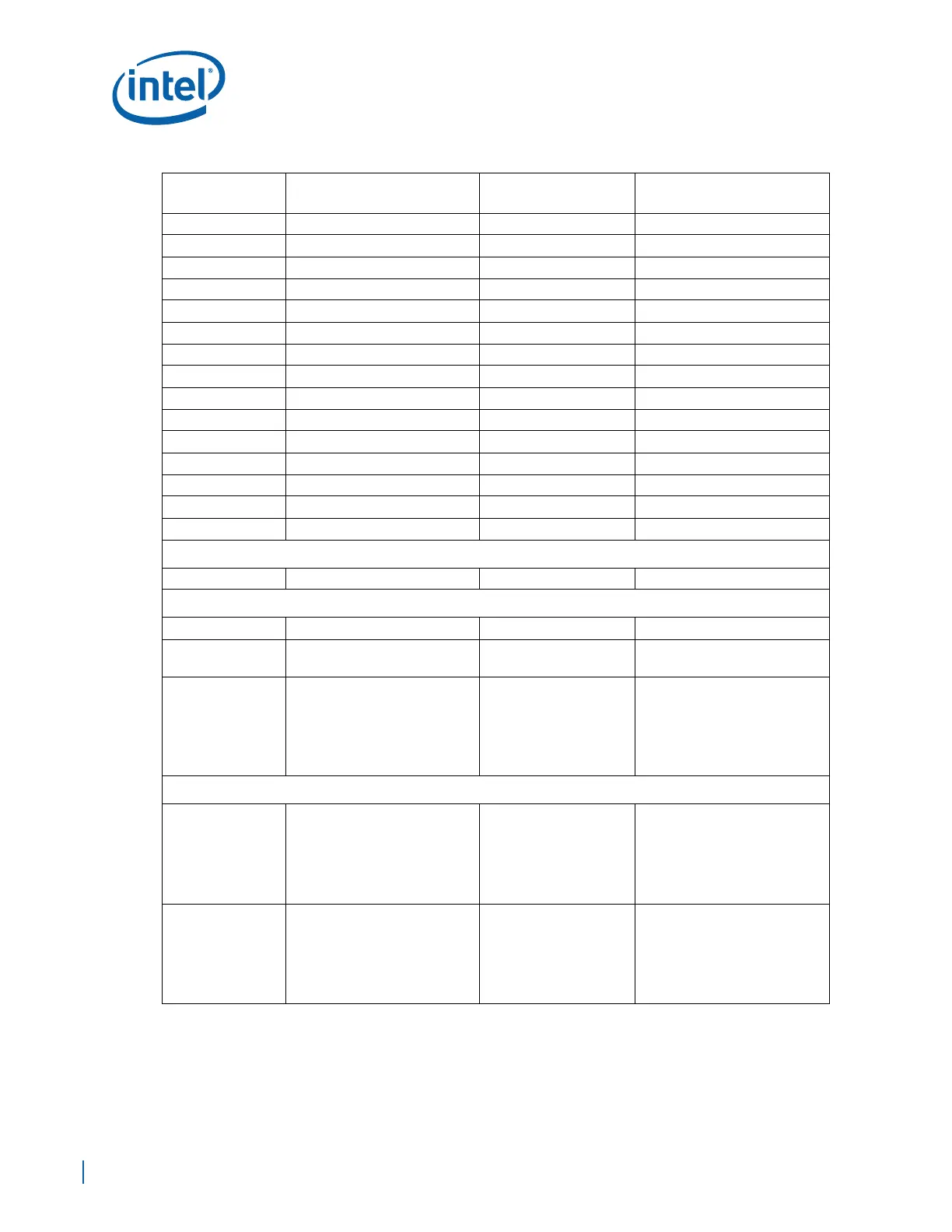
Table 97. Layout Checklist (Sheet 6 of 13)
Signal Name
Trace Geometry and
Impedance
Length Requirements Comments
 Loading...


