Intel
®
EP80579 Integrated Processor Product Line May 2010
Order Number: 320068-005US 275
Layout Checklist—Intel
®
EP80579 Integrated Processor Product Line
SPI_CS#
Zo = 50
Ω +/- 10%
Trace Width:
Microstrip: 4.5 mils
Stripline: 3.75 mils (L3/L8)
Airgap Spacing:
Spacing to other signals 7 mils
Routing Length LT:
Max = 16 in.
See Section 16.2.1, “SPI Routing
Guidelines”.
Place pull resistor close to the
SPI Flash device.
SPI_CLK
Zo = 50
Ω +/- 10%
Trace Width:
Microstrip: 4.5 mils
Stripline: 3.75 mils (L3/L8)
Airgap Spacing:
Spacing to other signals 7 mils
Routing Length LT:
Max = 16 in.
See Section 16.2.1, “SPI Routing
Guidelines”.
Place pull resistor close to the
SPI Flash device.
System Management Bus (SMBus) Interface
SMBSDA,
SMBSCL
Zo = 50
Ω +/- 10%
INTRUDER# Zo = 50
Ω +/- 10%
SMLINK[1:O] Zo = 50 Ω +/- 10%
SMBALERT# Zo = 50
Ω +/- 10%
Serial Interface Unit (UART) Interface
SIU_RXD[2:1]
SIU_TXD[2:1]
SIU_CTS[2:1]#
SIU_DSR[2:1]#
SIU_DCD[2:1]#
SIU_RI[2:1]#
SIU_DTR[2:1]#
SIU_RTS[2:1]#
Zo = 50
Ω +/- 10%
UART_CLK Zo = 50
Ω +/- 10%
Place the 33 Ω ± series
resistor as close as
possible to the source.
Isolate UART_CLK from USB_CLK
(CLK48) through the series
resistors
Serial ATA (SATA) Interface
SATA_TXp[1:0]
SATA_TXn[1:0]
SATA_RXp[1:0]
SATA_RXn[1:0]
Zdiff = 90
Ω +/- 10%
Trace Width:
Brakeout Trace Width 4 mils
Microstrip: 4.75 mils
Stripline: 4.5 mils (L3/L8)
Airgap Spacing:
Brakeout spacing Min=4mils
Microstrip: 5.25 mils
Stripline: 5.5 mils
Spacing between Pairs, the
greater of the two
Microstrip: 25 mils
Stripline: 20 mils
Breakout L1:
Max = 0.40 in.
Length L2:
Microstrip
Min=1.5 in, Max=5.75 in
Strip Line
Min=1.15 in, Max=4.75 in
Length
L3 Max=0.350 in
Inter-pair length
matching: +/- 5 mils
See Section 11.2, “SATA
Transmit and Receive Signals –
SATA_TXp[1:0], SATA_TXn[1:0],
SATA_RXp[1:0],
SATA_RXn[1:0]”.
It is recommended to place the
AC coupling capacitors close to
the connector for optimal signal
quality.
2 Vias Max
SATA_RBIAS
SATA_RBIAS#
Zo = 50
Ω +/- 10%
Routing Length LT:
Max = 0.5 in.
Place the RBIAS (resistor bias)
as close as possible to EP80579
.
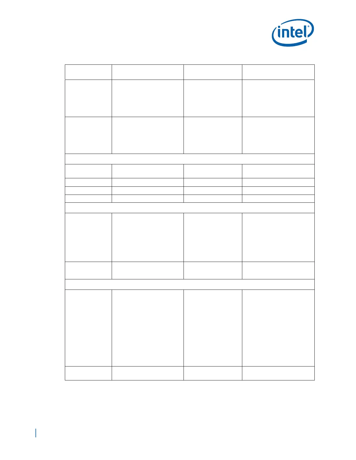
Table 97. Layout Checklist (Sheet 7 of 13)
Signal Name
Trace Geometry and
Impedance
Length Requirements Comments

 Loading...


