Intel
®
EP80579 Integrated Processor Product Line—Layout Checklist
Intel
®
EP80579 Integrated Processor Product Line
Platform Design Guide May 2010
278 Order Number: 320068-005US
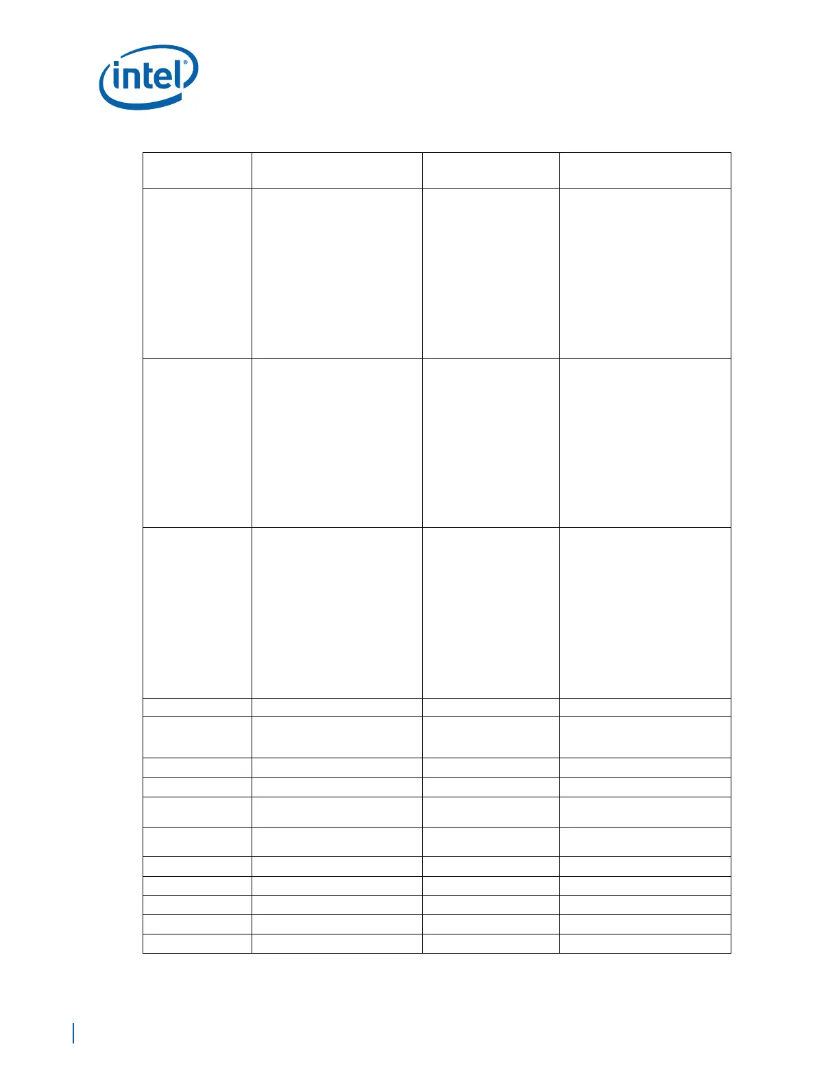
GBE0_TxDATA[3:0]
GBE1_TxDATA[3:0]
GBE2_TxDATA[3:0],
GBE0_TxCTL,
GBE1_TxCTL,
GBE2_TxCTL
Zo = 55
Ω +/- 10%
Trace Width:
Brakeout Trace Width 4 mils
Microstrip: 4.5 mils
Stripline:
3.75 mils (L3/L8)
5 mils (L5/L6)
Airgap Spacing:
Brakeout spacing Min=4mils
Spacing between Data\Control
Stripline Min = 12mils
Microstrip Min = 18mils
Breakout:
EP80579 Max = 500mils.
PHY Max = 300mils.
Total Data Routing:
+/- 50 mils of Total Clock
Routing.
Pull Up Trace Length
Max=0.4 in.
See Section 19.6.1.2, “GbE
Transmit Data\Control Topology”.
Place pull-up resistors close to
PHY device.
GBE0_RxCLK,
GBE1_RxCLK,
GBE2_RxCLK
Zo = 50
Ω +/- 10%
Trace Width:
Brakeout Trace Width 4 mils
Microstrip: 5.5 mils
Stripline:
4.5 mils (L3/L8)
6 mils (L5/L6)
Airgap Spacing:
Brakeout spacing Min=4mils
Spacing to other clock signals
Stripline Min = 20mils
Microstrip Min = 25mils
Breakout:
EP80579 Max = 500mils.
PHY Max = 300mils.
Total Clock Routing:
Microstrip 1 to 7.8 in
Stripline 1 to 7.8 in.
Pull Up Trace Length
Max=0.625 in.
See Section 19.6.2.1, “GbE
Receive Clock Topology”.
Place pull-up resistors close to
EP80579 device.
GBE0_RxDATA[3:0]
GBE1_RxDATA[3:0]
GBE2_RxDATA[3:0]
GBE0_RxCTL,
GBE1_RxCTL,
GBE2_RxCTL
Zo = 50
Ω +/- 10%
Trace Width:
Brakeout Trace Width 4 mils
Microstrip: 5.5 mils
Stripline:
4.5 mils (L3/L8)
6 mils (L5/L6)
Airgap Spacing:
Brakeout spacing Min=4mils
Spacing between Data\Control
Stipline Min = 12mils
Microstrip Min = 18mils
Breakout:
EP80579 Max = 500mils.
PHY Max = 300mils.
Total Data Routing:
+/- 50 mils of Total Clock
Routing.
Pull Up Trace Length
Max=0.625 in.
See Section 19.6.2.2, “GbE
Receive Data\Control Topology”.
Place pull-up resistors close to
EP80579 device.
MDC Zo = 50
Ω +/- 10%
MDIO Zo = 50
Ω +/- 10%
•See Section 19.5.1, “GbE
Ethernet Interface — RGMII
Mode”.
GBE_REFCLK Zo = 50
Ω +/- 10%
GBE_REFCLK_RMII Zo = 50 Ω +/- 10%
GBE_RCOMPP Zo = 50
Ω +/- 10%
Place the RCOMPP resistor as
close as possible EP80579
.
GBE_RCOMPN Zo = 50 Ω +/- 10%
Place the RCOMPN resistor as
close as possible EP80579
.
EEDO Zo = 50 Ω +/- 10%
EEDI Zo = 50 Ω +/- 10%
EECS Zo = 50
Ω +/- 10%
EESK Zo = 50
Ω +/- 10%
GBE_PME_WAKE Zo = 50
Ω +/- 10%
Table 97. Layout Checklist (Sheet 10 of 13)
Signal Name
Trace Geometry and
Impedance
Length Requirements Comments

 Loading...


