Intel
®
EP80579 Integrated Processor Product Line May 2010
Order Number: 320068-005US 288
Schematics Checklist—Intel
®
EP80579 Integrated Processor Product Line
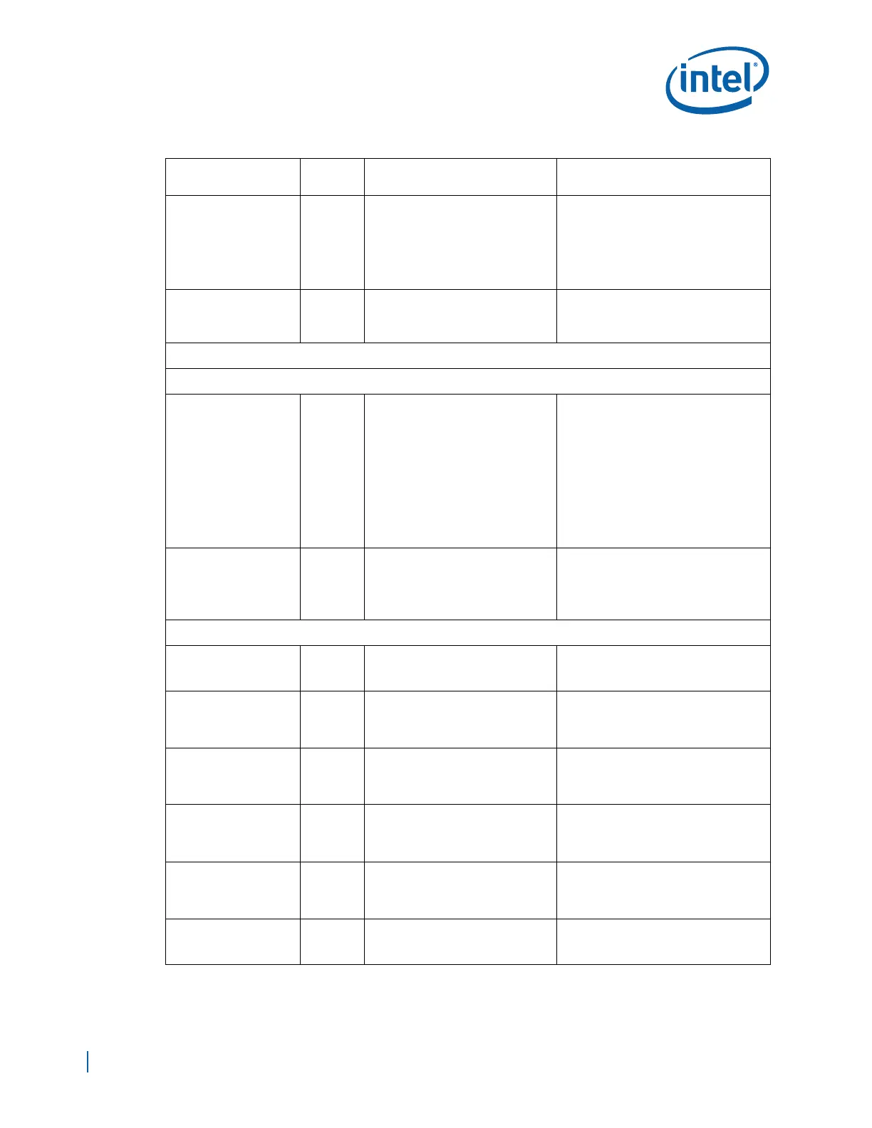
PEA_CLKp,
PEA_CLKn
I
• Connect to one of 100 MHz
differential clock outputs from
CK410 Clock device through a
33 Ω ±5% series resistor.
• Terminate to GND through a
49.9Ω ±1% resistor
Note:
•Connect PEA_CLK(p/n) to a
100 MHz differential clock source
even if the PCI-E port is not used or
not connected to an interfacing
device.
•See Section 2.3
PEA_ICOMPI,
PEA_ICOMPO,
PEA_RCOMPO
I
• Tie these signals together and
connect to EP80579 1.2V (VCC)
supply through a 24.9 Ω ±1%
resistor.
Integrated I/O Controller Hub (IICH) Interface
Real Time Clock (RTC)
RTCX1,
RTCX2
I/O
RTC Crystal I/O
• Connect a 32.768 kHz Crystal
Oscillator across these pins
with a 10 MΩ resistor.
• Decouple both RTCX1 and
RTCX2 with 15 pF ±5%, 50V
capacitors to GND.
Note:
• The capacitor and resistor values in
this document is based on the
crystal selected for the
Development Board.
• The exact capacitor and resistor
values for any design must be
based on the recommendations
provided by the crystal maker for
the crystal selected for the design
•See Figure 130 for further
guidelines
RTEST# I
RTC Test Enable
• Connect pin to a 20KΩ ± 5%
resistor to VCCRTC.
• Connect to a 1.0µF ± 5%
capacitor to GND.
See Section 15.1.5.
General Purpose I/O (GPIO) and Interrupts Interface
GPIO[1:0] I • Input Only (GPI)
• Must be pulled high through a 10
KΩ resistor if not used
• Resides in Core Power Well
GP2_PIRQE# I
• Input Only if used as GPI.
• Can be used as PIRQE#.
• Must be pulled high through a 10
KΩ resistor if not used or used in
PIRQ mode.
• Resides in Core Power Well
GP3_PIRQF# I
• Input Only if used as GPI.
• Can be used as PIRQF#.
• Must be pulled high through a 10
KΩ resistor if not used or used in
PIRQ mode.
• Resides in Core Power Well
GP4_PIRQG# I
• Input Only if used as GPI.
• Can be used as PIRQG#.
• Must be pulled high through a 10
KΩ
resistor if not used or used in
PIRQ mode
• Resides in Core Power Well
GP5_PIRQH# I
• Input Only if used as GPI.
• Can be used as PIRQH#.
• Must be pulled high through a 10
KΩ resistor if not used or used in
PIRQ mode
• Resides in Core Power Well
GPIO[7:6] I • Input Only (GPI)
• Must be pulled high through a 10
KΩ resistor if not used
• Resides in Core Power Well
Table 100. Schematic Checklist (Sheet 5 of 26)
Checklist Items
I/O Type
(Default)
Recommendations Comments